Cutter blunting machine

A passivation machine and cutting tool technology, which is applied in the direction of manufacturing tools, grinding machine parts, surface polishing machine tools, etc., can solve the problems of high passivation cost, and achieve the effects of low cost, simple structure and convenient implementation

Active Publication Date: 2016-02-03
江苏仓环铜业股份有限公司
View PDF8 Cites 14 Cited by
  • Summary
  • Abstract
  • Description
  • Claims
  • Application Information

AI Technical Summary

Problems solved by technology

[0003] However, the equipment used in the above-mentioned mechanical passivation is relatively expensive, and the cost of passivation is relatively high

Method used


Image

  • Cutter blunting machine

Examples


Embodiment Construction

[0019] Preferred embodiments of the present invention will be described in detail below in conjunction with the accompanying drawings.

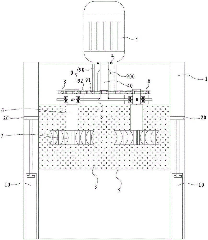
[0020] Such as figure 1 As shown, the tool passivation machine provided in this embodiment includes a frame 1, an abrasive tank 2 capable of moving up and down along the height direction of the frame 1, an abrasive material 3 contained in the abrasive tank 2, and is arranged on the frame. 1 and the drive motor 4 with the output shaft 40 facing vertically downward, the output frame 5 fixed on the lower end of the output shaft 40, the rotating shaft arranged on the output frame 5 parallel to the output shaft 40 and capable of rotating around its own axis direction 6, wherein the lower end of the rotating shaft 6 can be detachably installed with the tool 7 to be passivated, when the tool passivation machine is working, the lower end of the rotating shaft 6 and the tool 7 to be passivated extend into the abrasive tank 2 and drive The motor 4 dri...


PUM


Abstract

The invention relates to a cutter blunting machine, which comprise a rack, a grinding material tank, a grinding material, a drive motor, an output frame and rotating shafts, wherein the grinding material tank is capable of vertically moving along the height direction of the rack for adjustment; the grinding material is contained in the grinding material tank; the drive motor is arranged on the rack and an output shaft of the drive motor is vertically downward; the output frame is fixed to the lower end of the output shaft; the rotating shafts are arranged in parallel with the output shaft and rotatably arranged on the output frame around the respective axes; a to-be-blunted cutter is detachably mounted on the lower end parts of the rotating shafts; and when the cutter blunting machine works, the lower end parts of the rotating shafts and the to-be-blunted cutter stretch into the grinding material tank; the drive motor drives the rotating shafts to rotate and revolve on own axes, so that the cutter is blunted by the grinding material. According to the cutter blunting machine, the rotating shafts rotate around the output shaft of the drive motor and revolve on own axes, and the cutter is driven to rotate inside the grinding material tank provided with the grinding material, so that the cutter is blunted. The cutter blunting machine has the advantages that the structure is simple; the implementation is convenient; and the cost is low.

Description

technical field [0001] The invention relates to a tool passivation machine. Background technique [0002] At present, in order to prolong the service life of the cutting tool, it is often necessary to passivate the sharp cutting edge, and most of the high-efficiency mechanical passivation methods are used in the market. Such as vibration passivation, medium passivation, abrasive slurry passivation, abrasive rubber wheel passivation, dry or wet sandblasting passivation, tumbling passivation and abrasive nylon brush passivation, etc. [0003] However, the equipment used in the above-mentioned mechanical passivation is relatively expensive, and the cost of passivation is relatively high. Contents of the invention [0004] In order to overcome the defects of the prior art, the object of the present invention is to provide a tool passivation machine with simple structure, convenient implementation and low cost. [0005] In order to achieve the above object, the present invent...

Claims


Application Information

Patent Timeline
Patent Type & Authority Applications(China)
IPC IPC(8): B24B31/00B24B31/12B24B47/12B24B3/00
CPCB24B3/00B24B31/003B24B31/12B24B47/12
Inventor 李树刚王泽俊郭世河王明星姚翠翠张鹏遆同生朱建帅
Owner 江苏仓环铜业股份有限公司
Why Eureka
Try Eureka