Cutting machine

A technology for cutting machines and cutting parts, which is applied in the direction of sawing equipment, sawing components, and machine tools suitable for grinding the edge of workpieces, etc. It can solve the problems of high work intensity, low processing efficiency, and high requirements, and achieve reduced work intensity. The effect of improving processing efficiency and prolonging service life

Inactive Publication Date: 2016-02-03
CHONGQING AIBUTE FURNITURE
View PDF10 Cites 28 Cited by
  • Summary
  • Abstract
  • Description
  • Claims
  • Application Information

AI Technical Summary

Problems solved by technology

[0003] The purpose of the present invention is to provide a cutting machine to improve the existing cutting machine with high requirements for operators, high working intensity and low processing efficiency.

Method used


Image

  • Cutting machine
  • Cutting machine
  • Cutting machine

Examples


Embodiment approach 1

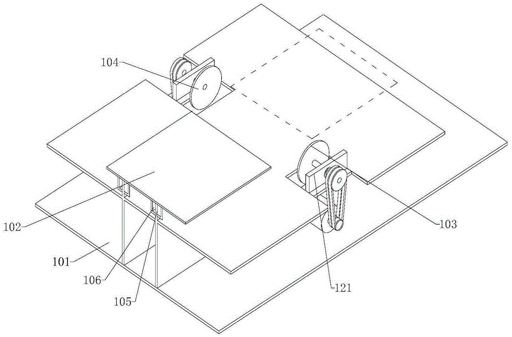
[0065] A cutting machine includes a frame body 101, a work table 102, a driving device, and a cutting member. The frame body is provided with a first guide rail 105, and the work table 102 is slidably connected to the first guide rail 105. The driving device is respectively connected with the worktable 102 and the cutting member, and the cutting member includes a first longitudinal cutting member 103 and a second longitudinal cutting member 104 that are symmetrically arranged. The first longitudinal cutting member 103 and the second longitudinal cutting member 104 Two longitudinal cutting members 104 are respectively connected to the frame body 101, the first longitudinal cutting member 103 is located at one side of the worktable 102 along the direction of the first guide rail 105, and the second longitudinal cutting member 104 is located at the The side of the worktable 102 away from the first longitudinal cutting member 103.

[0066] The workbench 102 is provided with a sliding...

Embodiment approach 2

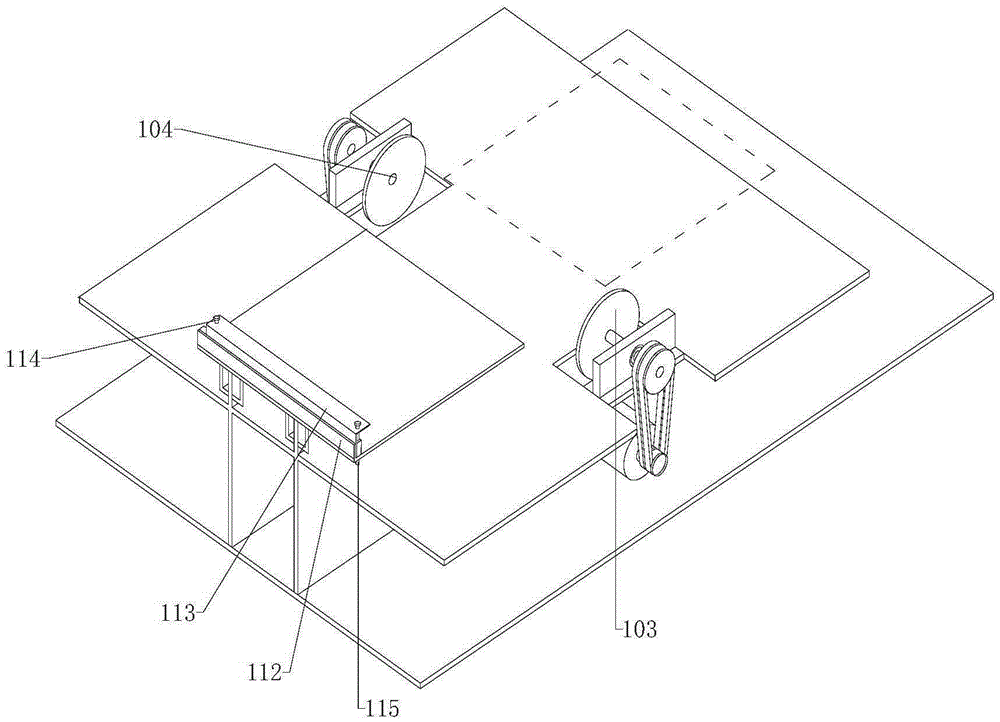
[0069] A cutting machine includes a frame body 101, a work table 102, a driving device, and a cutting member. The frame body is provided with a first guide rail 105, and the work table 102 is slidably connected to the first guide rail 105. The driving device is respectively connected with the worktable 102 and the cutting member, and the cutting member includes a first longitudinal cutting member 103 and a second longitudinal cutting member 104 that are symmetrically arranged. The first longitudinal cutting member 103 and the second longitudinal cutting member 104 Two longitudinal cutting members 104 are respectively connected to the frame body 101, the first longitudinal cutting member 103 is located at one side of the worktable 102 along the direction of the first guide rail 105, and the second longitudinal cutting member 104 is located at the The side of the worktable 102 away from the first longitudinal cutting member 103.

[0070] The workbench 102 is provided with a guiding...

Embodiment approach 3

[0076] A cutting machine includes a frame body 101, a worktable 102, a driving device, and a cutting member. The frame body is provided with a first guide rail 105, and the worktable 102 is slidably connected to the first guide rail 105. The driving device is respectively connected with the worktable 102 and the cutting member, and the cutting member includes a first longitudinal cutting member 103 and a second longitudinal cutting member 104 which are symmetrically arranged. The first longitudinal cutting member 103 and the second longitudinal cutting member 103 Two longitudinal cutting members 104 are respectively connected to the frame body 101, the first longitudinal cutting member 103 is located on one side of the worktable 102 along the direction of the first guide rail 105, and the second longitudinal cutting member 104 is located at the The side of the worktable 102 away from the first longitudinal cutting member 103.

[0077] The workbench 102 is provided with a sliding ...


PUM


Abstract

The invention provides a cutting machine and belongs to the field of mechanical devices. The cutting machine comprises a rack body, a workbench, a drive device and a cutting part, wherein the rack body is provided with a first guide rail; the workbench is in sliding connection with the first guide rail; the drive device is connected with the workbench and the cutting part; the cutting part comprise a first longitudinal cutting part body and a second longitudinal cutting part body which are arranged symmetrically; the first longitudinal cutting part body and the second longitudinal cutting part body are connected with the rack body; the first longitudinal cutting part body is located on one side of the workbench in the direction of the first guide rail; the second longitudinal cutting part body is located on the side, away from the first longitudinal cutting part body, of the workbench. According to the cutting machine, the drive device drives the workbench to slide along the first guide rail, so that cutting machining of planks is automatic, the cutting precision of the planks can be ensured without experienced operators, work intensity of the operators is also relieved, and the plank machining efficiency is improved.

Description

Technical field [0001] The invention relates to the field of mechanical devices, in particular to a cutting machine. Background technique [0002] The existing wood board processing procedure is to place the wood on the workbench, and then push the wood board into the cutter along the surface of the workbench to complete the cutting of the wood board. However, this processing procedure has higher requirements for the operator and needs to be rich. Experience can ensure the cutting accuracy of the wood board, and the manual operation has a strong work intensity and low processing efficiency. Summary of the invention [0003] The purpose of the present invention is to provide a cutting machine to improve the existing cutting machines that have high requirements on operators, high work intensity and low processing efficiency. [0004] The present invention is realized as follows: [0005] A cutting machine includes a frame body, a worktable, a driving device and a cutting part, [0006]...

Claims


Application Information

Patent Timeline
Patent Type & Authority Applications(China)
IPC IPC(8): B27B5/065B27B5/29B27B29/00B27G3/00B24B9/18
Inventor 周贤义
Owner CHONGQING AIBUTE FURNITURE
Why Eureka
Try Eureka