
Novel film blowing machine

A film blowing machine, a new type of technology, applied in the field of film production, can solve the problems of uneven force, large floor space, low efficiency, etc., and achieve the effects of ensuring quality, saving floor space, and convenient maintenance

Inactive Publication Date: 2016-02-03
嘉兴高正新材料科技股份有限公司
View PDF4 Cites 16 Cited by
  • Summary
  • Abstract
  • Description
  • Claims
  • Application Information

AI Technical Summary

Problems solved by technology

[0002] The film blowing machine is a machine that heats and melts plastic particles and then blows them into films. As various films are more and more widely used in production and life, the film blowing machine technology has also developed rapidly, but the traditional film blowing machine is adjustable. Poor performance, because the uneven force not only affects the shape of the film, but also makes the film thickness uneven when blowing the film; there is no intelligent control and detection function for the amount of air blown in. When more air is blown in, it will cause The film breaks, which seriously affects the quality of the film; and the produced plastic bag film itself is charged and generates static electricity, which not only affects the health of the staff, but also brings certain difficulties to the winding of the plastic bag film
[0003] Most of the existing film blowing machines occupy a large area and need to occupy a lot of effective use area in the workshop, and the screw of the existing film blowing machine often heats up during use, which affects product quality; Machines are operated manually, which is inefficient and error-prone, which is not conducive to the development of enterprises.

Method used


Image

  • Novel film blowing machine

Examples


Embodiment

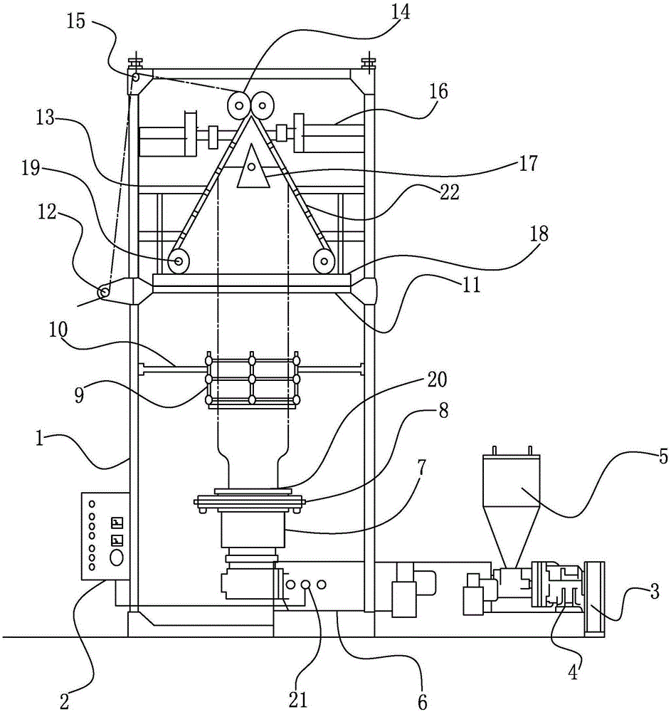
[0018] Example: such as figure 1 Shown: a new type of film blowing machine, including a frame 1, a transmission device, and a control panel 2; the control panel 2 is installed on the frame 1, and the transmission device is connected with a die head 7 at the center of the frame 1; This transmission device comprises the main engine triangular wheel 3, the gearbox 4, the feed hopper 5 and the main engine linkage shaft 6 which are arranged successively from right to left; There is a high-speed air ring 8, and the center of the high-speed air ring 8 is provided with a blowing core 20. By adjusting the blowing core 20 to adjust the center of the plastic bag, it not only ensures the uniform thickness of the plastic bag film, but also facilitates the transmission of the plastic bag film The upper end of the high-speed air ring 8 is equipped with a limit plate 9 of adjustable size, and the limit plate 9 moves up and down by being arranged on the limit plate holder 10 arranged at the tw...


PUM

PropertyMeasurementUnit
angleaaaaaaaaaa
heightaaaaaaaaaa

Abstract

The invention relates to a novel film blowing machine which comprises a rack, a conveying device and a control panel. The control panel is installed on the rack, and the conveying device is connected with a mould head at the center of the rack. The conveying device comprises a main machine triangular wheel, a gearbox, a feed hopper and a main machine linkage shaft which are sequentially arranged from right to left. The main machine linkage shaft is in transmission connection with the mould head. A high-speed air ring is arranged at the upper end of the mould head. A blow molding core is arranged at the center of the high-speed air ring. By means of the novel film blowing machine, a limiting plate is installed on the rack in a sliding mode and can be pushed up and down, occupied area is saved, and maintenance is convenient. The control panel is adopted so that a full-automatic production mode can be achieved, and the quality of products is guaranteed. Besides, an adjusting handle and an edge folding device are arranged so that the situation that a film face rubs with a herringbone-shaped clamping plate face, wrinkles are generated, and accordingly product quality is influenced can be prevented.

Description

technical field [0001] The invention relates to the technical field of film production, in particular to a novel film blowing machine. Background technique [0002] The film blowing machine is a machine that heats and melts plastic particles and then blows them into films. As various films are more and more widely used in production and life, the film blowing machine technology has also developed rapidly, but the traditional film blowing machine is adjustable. Poor performance, because the uneven force not only affects the shape of the film, but also makes the film thickness uneven when blowing the film; there is no intelligent control and detection function for the amount of air blown in. When more air is blown in, it will cause The film cracks, which seriously affects the quality of the film; and the produced plastic bag film itself is charged to generate static electricity, which not only affects the health of the staff, but also brings certain difficulties to the winding...

Claims


Application Information

Patent Timeline
Patent Type & Authority Applications(China)
IPC IPC(8): B29C55/28
CPCB29C55/28
Inventor 王鹏郑泓唐琦琦甄万清时艳南聂福
Owner 嘉兴高正新材料科技股份有限公司
Learn More