Multi-rotor-wing unmanned plane

A multi-rotor unmanned aerial vehicle and body technology, applied in the field of unmanned aerial vehicles, can solve the problems of poor horizontal rotation stability, weak anti-interference ability, and poor flight stability, so as to enhance stability, shorten the time for adjusting balance, and ensure flight stability. stable effect

Inactive Publication Date: 2016-02-03
JIYI ROBOT SHANGHAI
View PDF7 Cites 21 Cited by
  • Summary
  • Abstract
  • Description
  • Claims
  • Application Information

AI Technical Summary

Problems solved by technology

[0007] In view of the defects in the prior art, the purpose of the present invention is to provide a multi-rotor UAV to solve the problems of poor environmental ada

Method used


Image

  • Multi-rotor-wing unmanned plane
  • Multi-rotor-wing unmanned plane
  • Multi-rotor-wing unmanned plane

Examples


Embodiment 1

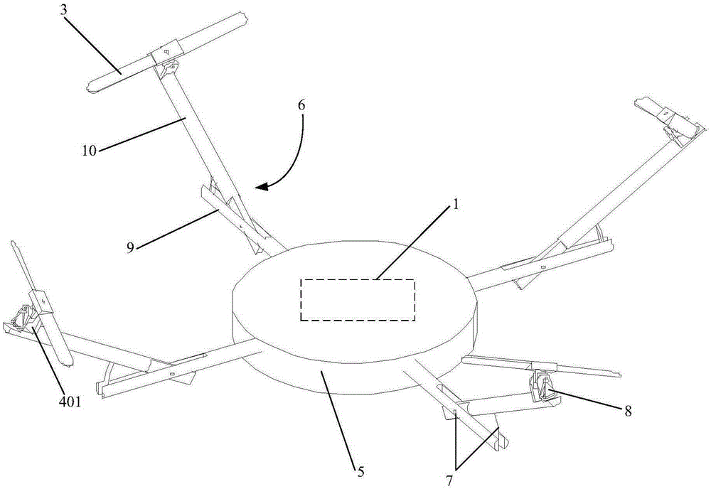
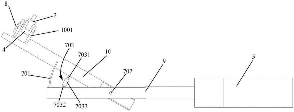
[0044] Such as figure 2 As shown, the first connecting member 7 includes: a reed 701, a pin shaft 702 and a tension member 703. The pin shaft 702 is arranged on the side close to the body 4 to connect with the strut 9 and the swing rod 10 respectively, and the reed 701 is arranged away from One side of the body 5 is respectively connected with the strut 9 and the swing rod 10 , the tension member 703 is arranged between the pin shaft 702 and the reed 701 , and the tension member 703 is respectively connected with the strut 9 and the swing rod 10 .

[0045] The tension member 703 includes an upper screw 7031, a lower screw 7032 and a threaded tube 7033. The upper screw 7031 is connected with the swing rod 10, the lower screw 7032 is connected with the strut 9, and the threaded tube 7033 is connected with the upper screw 7031 and the lower screw 7032 respectively. The upper screw 7031 and the lower screw 7032 are provided with external threads, and the upper and lower ends of t...

Embodiment 2

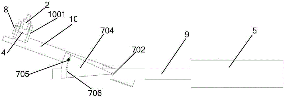
[0049] Such as image 3 As shown, the first connecting member 7 includes: a fan-shaped block 704, a pin shaft 702 and a latch 705. The center of the fan-shaped block 704 is arranged on the side close to the body 5 and is respectively connected to the strut 9 and the swing rod 10 through the pin shaft 702. The fan-shaped The arc end of the block 704 is arranged on the side away from the body 5, and the lower plane of the sector block 704 is connected with the swing rod 10, and a plurality of positioning holes 706 are arranged on the arc inner side of the arc end of the sector block 704, and a screw thread is provided on the latch 705. Correspondingly, a threaded hole is provided at a position corresponding to the positioning hole on the swing rod 10 , and the pin 705 is threadedly connected with the swing rod 10 through the positioning hole 706 .

[0050] The process of adjusting the inclination angle between the propeller 3 and the body 5 using the first connector structure of...

Embodiment 3

[0053] Such as Figure 4 As shown, the first connecting member 7 includes: a pin shaft 702, a push rod 707, a slider 708 and a locking block 709, the pin shaft is arranged on the side close to the body 5 and connected with the strut 9 and the swing bar 10 respectively, and the slider 708 It is arranged on the side far away from the body 5 and connected with the support rod 9. The support rod 9 is provided with external threads, and the locking block 709 is provided with internal threads. Connected, the push rod 707 is connected with the swing rod 10 and the slider 708 respectively.

[0054] The process of adjusting the inclination angle between the propeller 3 and the body 5 using the first connector structure of this embodiment is as follows:

[0055] When the external wind force is strong and the inclination angle between the propeller 3 and the body 5 needs to be increased, the locking block 709 on the inner side of the slide block 708 is rotated inwardly, and then the sli...


PUM


Abstract

The invention provides a multi-rotor-wing unmanned plane which comprises a flight control assembly, a rack, a plurality of motors, a plurality of motor seats and a plurality of propellers. The rack comprises a machine body, a plurality of supports, a plurality of first connectors and a plurality of second connectors. The flight control assembly is arranged on the machine body, each support comprises a supporting rod and a swing rod, the supporting rods are connected with the machine body, one end of each swing rod is movably connected with the corresponding supporting rod through the corresponding first connector, and the included angles between the supporting rods and the swing rods are changeable; the other ends of the swing rods are provided with motor seat mounting portions, the motor seats are provided with connection shafts, the connection shafts are connected with the motor seat mounting portions, the second connectors are connected with the connection shafts and the motor seat mounting portions respectively, the motors are connected with the motor seats, and the propellers are connected with the motors. The multi-rotor-wing unmanned plane has the advantages of being simple in structure, flexible and convenient in angle adjustment operation, wide in application range, high in flight stability and high in interference resistance.

Description

technical field [0001] The invention relates to an unmanned aerial vehicle, in particular to a multi-rotor unmanned aerial vehicle with stable operation. Background technique [0002] In recent years, multi-rotor UAVs have become one of the hot spots in the research field of emerging micro UAVs. Multi-rotor drones have the advantages of small size, light weight, low cost, flexible operation and high safety, and can be widely used in aerial photography, detection, search and rescue, exploration and other fields. [0003] The multi-rotor drone is driven by multiple independent motors, the motors are connected to the frame, and the propellers are connected to the motors. Generally, the frame and the fuselage of the multi-rotor UAV are arranged in the same plane, and the propellers are arranged horizontally. Therefore, the propeller of the multi-rotor UAV is set in parallel with the fuselage. This structure responds slowly to external disturbances and takes a long time to adju...

Claims


Application Information

Patent Timeline
IPC IPC(8): B64C27/08B64C1/06B64C27/52
Inventor 周剑锋王凯
Owner JIYI ROBOT SHANGHAI
Why Eureka
Try Eureka