
Selective etching method and preparation method of nano needle tip structure

A selective, needle-tip technology, applied in the semiconductor field, can solve problems such as the complexity of the nano-tip structure process

Inactive Publication Date: 2019-07-12
INST OF MICROELECTRONICS CHINESE ACAD OF SCI
View PDF9 Cites 4 Cited by
  • Summary
  • Abstract
  • Description
  • Claims
  • Application Information

AI Technical Summary

Problems solved by technology

[0003] The main purpose of the present invention is to provide a selective etching method and a method for preparing a nano-tip structure, so as to solve the problem of complex processes in the prior art for preparing a nano-tip structure

Method used


Image

  • Selective etching method and preparation method of nano needle tip structure
  • Selective etching method and preparation method of nano needle tip structure
  • Selective etching method and preparation method of nano needle tip structure

Examples


preparation example Construction

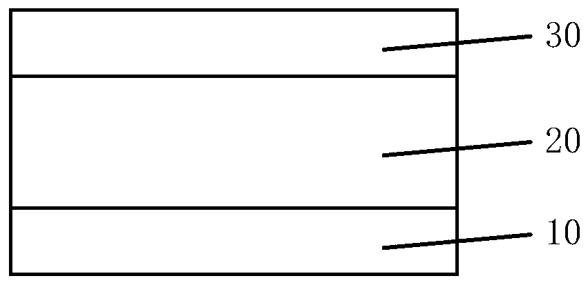
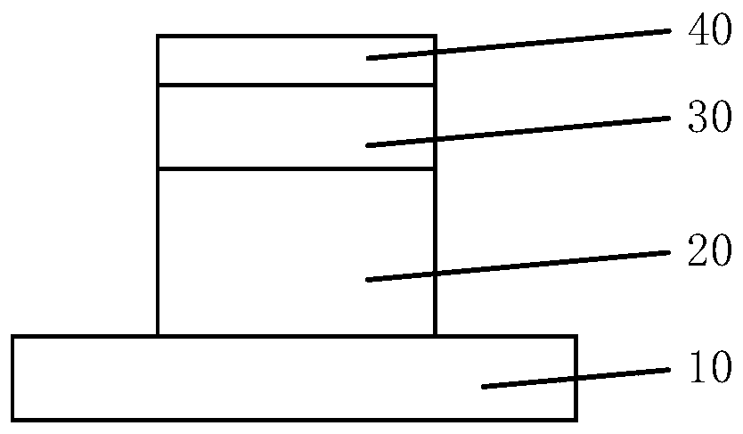
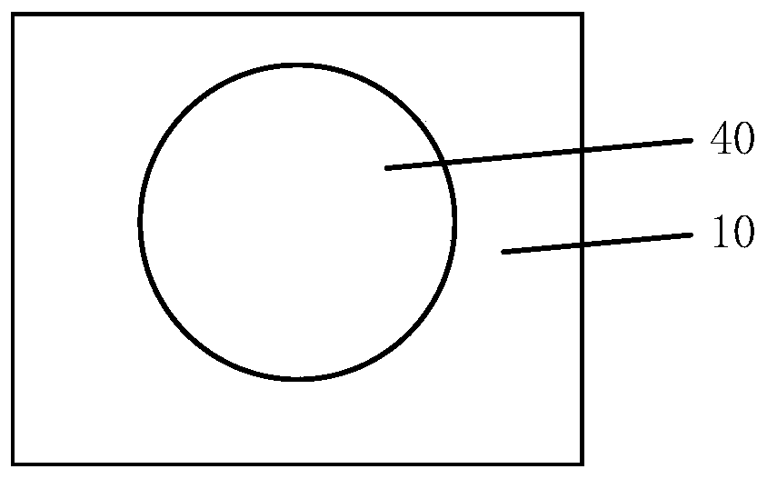
[0041] According to another aspect of the present invention, there is also provided a method for preparing a nano-needle structure, such as Figure 1 to Figure 6 As shown, it includes the following steps: using the above-mentioned selective etching method to form the first material layer 20 into the nano-tip structure 220; removing the second material layer 30 to expose the top of the nano-tip structure 220.

[0042] The above selective etching method includes: S1, sequentially forming the first material layer 20 and the second material layer 30 on the substrate 10, such as figure 1 As shown, wherein the isotropic etching selectivity ratio of the first material layer 20 to the second material layer 30 is greater than 1, the material of the first material layer 20 is a material containing doping elements, and the material containing doping elements includes doping element, and the concentration of the doped element increases linearly along the thickness direction of the first m...

Embodiment 1

[0055] The preparation method of the nano-needle tip structure provided by this embodiment is as follows: Figure 1 to Figure 6 As shown, the process flow is as follows Figure 9 shown, including the following steps:

[0056] SiGe and Si are sequentially deposited on the substrate 10 of single crystal silicon to form the first material layer 20 and the second material layer 30, and the concentration of Ge along the thickness direction of the first material layer 20 is linearly increasing, such as figure 1 shown;

[0057] Deposit SiO on the second material layer 30 2 To form a mask material layer, the mask material layer is formed into a mask layer 40 by using a photolithography process and an etching process. The mask layer 40 has the same size as the bottom of the nano needle tip structure to be formed. Through the mask layer 40 Etching the first material layer 20 and the second material layer 30 to form protrusions on the substrate surface, such as figure 2 with image...

Embodiment 2

[0061] The difference between the preparation method provided in this example and Example 1 is that after the nano-needle structure is formed, the preparation method further includes the following steps:

[0062] An evaporation or sputtering process is used to cover a conductive film on the surface of the nano needle tip structure to form a conductive needle tip structure, and the conductive film may be an Au layer or a Pt layer.

[0063] The above conductive tip structure can be applied to conductive probes or bio-electrodes.


PUM


Abstract

The invention provides a selective etching method and a preparation method of a nano needle tip structure. The selective etching method comprises the following steps that a first material layer and asecond material layer are sequentially formed on a substrate, the isotropic etching selection ratio of the first material layer to the second material layer is larger than 10, the first material layercontains doping elements, and the concentration of the doping elements is linearly increased in the thickness direction of the first material layer; and selective isotropic etching is performed on the first material layer, wherein the etching rate of the selective isotropic etching has a positive linear relationship with the concentration of the doping elements, so as to complete the etching of the outer wall of the first material layer. According to the invention, the positive linear relationship between the etching rate in the etching process and the concentration of the doping elements inthe to-be-etched material is utilized, so that sloped sidewalls opposite to the increasing direction of the concentration is obtained; by the adoption of the selective etching method, the nano needletip structure with high sharpness can be obtained, and the size, the shape and the angle of the needle tip structure can be flexibly adjusted.

Description

technical field [0001] The invention relates to the technical field of semiconductors, in particular to a selective etching method and a preparation method of a nano needle tip structure. Background technique [0002] Nanoscale needle tips are widely used, such as STM probes of tunneling scanning electron microscopes in scanning tunneling microscopes, cell micromanipulation in medicine, and microprocessing in special manufacturing industries. Specific surface area increases sensitivity. Electrochemical etching, mechanical shearing, field evaporation, focused ion milling and other methods are often used to prepare nano-tips. The methods are complicated, the production cost is high, and it is difficult to mass-produce. Contents of the invention [0003] The main purpose of the present invention is to provide a selective etching method and a method for preparing a nano-tip structure, so as to solve the problem of complex processes in the prior art for preparing a nano-tip st...

Claims


Application Information

Patent Timeline
Patent Type & Authority Applications(China)
IPC IPC(8): B81B1/00B81C1/00
CPCB81B1/008B81C1/00111B81C1/00404
Inventor 李俊杰王桂磊李永亮周娜杨涛傅剑宇李俊峰吴振华殷华湘朱慧珑王文武
Owner INST OF MICROELECTRONICS CHINESE ACAD OF SCI
Learn More