Connecting rod of engine

An engine connecting rod and connecting rod cover technology, which is applied to connecting rods, mechanical equipment, shafts and bearings, etc., can solve problems such as affecting the working efficiency of the engine, adverse effects on the public environment, and cumbersome replacement of the crankshaft. Ignition start, the effect of increasing the ignition range

Inactive Publication Date: 2012-07-04
李合理
View PDF6 Cites 5 Cited by
  • Summary
  • Abstract
  • Description
  • Claims
  • Application Information

AI Technical Summary

Problems solved by technology

[0002] The connecting rod is a rod whose two ends are respectively hinged with the driving and driven components to transmit motion and force. The engine connecting rod is used to connect the piston and crankshaft in the engine. The existing connecting rod cannot make good use of the principle of leverage. When the flywheel on the engine rotates to 16°-20° before the top dead center, the fuel injector supplies oil to the cylinder. At the moment of deflagration at the top dead center, the piston, connecting rod and the top of the crankshaft are in a straight line. At this time, the piston Push the connecting rod down to move, and the connecting rod bush on the big end of the connecting rod connected to the crankshaft will have an instantaneous strong impact on the crankshaft, which will wear the crankshaft. Long-term work will easily cause the crankshaft to be round or even damaged, and the replacement of the crankshaft is not only cumbersome And the cost is very high. In addition, because the existing connecting rod moves downward at the moment of fuel deflagration, the tops of the piston, connecting rod and crankshaft are in a straight line, and the connecting rod hinders the movement of the piston to a certain extent, and the noise generated Larger, thus affecting the working efficiency of the engine, wasting resources, and causing adverse effects on the public environment

Method used


Image

  • Connecting rod of engine
  • Connecting rod of engine

Examples


Embodiment 1

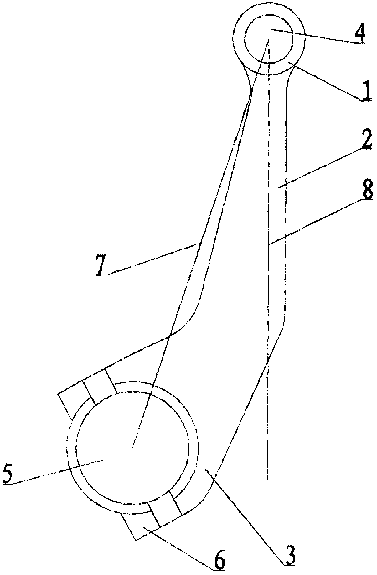
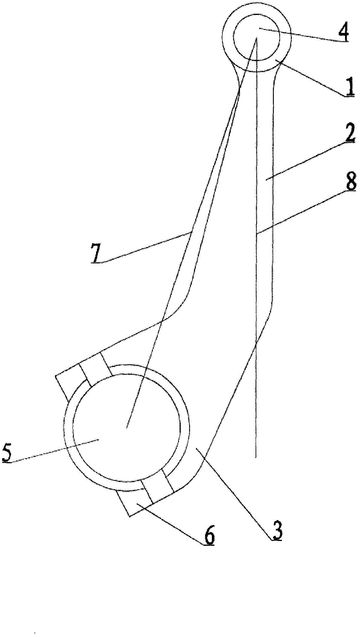
[0012] Such as figure 1 As shown, a connecting rod of an engine includes a connecting rod small end 1 provided with a piston shaft mounting hole 4, a crankshaft mounting seat 3 integrally cast with the connecting rod small end 1 through the rod body 2, and is mounted on the crankshaft mounting seat 3. There is a connecting rod cover 6, the connecting rod cover 6 and the crank mounting seat 3 form the crankshaft mounting hole 5, and the end of the crankshaft mounting seat 3 of the shaft 2 is bent to one side of the shaft 2 in an L-shape. The piston shaft mounting hole 4 An included angle is provided between the line 7 between the center of the circle and the center of the crankshaft mounting hole 5, and the vertical line 8 passing through the center of the circle of the piston shaft mounting hole 4, and the angle is 10°.

Embodiment 2

[0014] Such as figure 1 As shown, a connecting rod of an engine includes a connecting rod small end 1 with a piston shaft mounting hole 4, a crankshaft mounting seat 3 integrally cast with the connecting rod small end 1 through a rod body 2, and is installed on the crankshaft mounting seat 3. There is a connecting rod cover 6, the connecting rod cover 6 and the crank mounting seat 3 form the crankshaft mounting hole 5, and the end of the crankshaft mounting seat 3 of the shaft 2 is bent to one side of the shaft 2 in an L-shape. The piston shaft mounting hole 4 An included angle is provided between the line 7 between the center of the circle and the center of the crankshaft mounting hole 5, and the vertical line 8 passing through the center of the circle of the piston shaft mounting hole 4, and the angle is 15°.

Embodiment 3

[0016] Such as figure 1 As shown, a connecting rod of an engine includes a connecting rod small end 1 with a piston shaft mounting hole 4, a crankshaft mounting seat 3 integrally cast with the connecting rod small end 1 through a rod body 2, and is installed on the crankshaft mounting seat 3. There is a connecting rod cover 6, the connecting rod cover 6 and the crank mounting seat 3 form the crankshaft mounting hole 5, and the end of the crankshaft mounting seat 3 of the shaft 2 is bent to one side of the shaft 2 in an L-shape. The piston shaft mounting hole 4 An included angle is provided between the line 7 between the center of the circle and the center of the crankshaft mounting hole 5, and the vertical line 8 passing through the center of the circle of the piston shaft mounting hole 4, and the angle is 25°.

[0017] When the piston moves upwards to the top dead center, the crankshaft is driven by the connecting rod of the engine to tilt in the direction of rotation. When t...


PUM


Abstract

The invention discloses a connecting rod of an engine, which solves the problem of serious abrasion to a crankshaft, and is capable of improving the working efficiency of the engine. The connecting rod of the engine comprises a connecting rod small end provided with a mounting hole of a piston shaft, and a mounting seat of the crankshaft which is cast into a whole together with the connecting rod small end by a rod body; the mounting seat of the crankshaft is provided with a connecting rod cover; a mounting hole of the crankshaft is formed by the connecting rod cover and the mounting seat of the crankshaft; the end of the mounting seat of the crankshaft of the rod body is bended towards the side of the rod body and is in an L shape; and the included angle between the connecting line of the centre of a circle of the mounting hole of the piston shaft and the centre of a circle of mounting hole of the crankshaft and the vertical line passing through the centre of a circle of the mounting hole of the piston shaft is within the range 10-25 degrees. The connecting rod of the engine has the advantages of being simple in structure, strong in practicability and convenient to popularize, and being capable of improving the working efficiency of the engine by better utilizing the lever principle.

Description

technical field [0001] The invention belongs to the technical field of engine parts, and in particular relates to an engine connecting rod which solves the serious problem of crankshaft wear and can effectively improve the working efficiency of the engine. Background technique [0002] The connecting rod is a rod whose two ends are respectively hinged with the driving and driven components to transmit motion and force. The engine connecting rod is used to connect the piston and crankshaft in the engine. The existing connecting rod cannot make good use of the principle of leverage. When the flywheel on the engine rotates to 16°-20° before the top dead center, the fuel injector supplies oil to the cylinder. At the moment of deflagration at the top dead center, the piston, connecting rod and the top of the crankshaft are in a straight line. At this time, the piston Push the connecting rod down to move, and the connecting rod bush on the big end of the connecting rod connected t...

Claims


Application Information

Patent Timeline
Patent Type & Authority Applications(China)
IPC IPC(8): F16C7/02
Inventor 李合理曹美丽李龙李建楠李香梅
Owner 李合理
Why Eureka
Try Eureka