Gas cutting early stage monitoring method

A technology of gas intrusion and monitoring device, which is applied in surveying, earthwork drilling, wellbore/well components, etc., can solve the problems of rapid determination and control of unfavorable gas intrusion, not belonging to early monitoring, and large limitations, and is easy to popularize. Use, reduce production costs, increase the effect of applicability

Inactive Publication Date: 2016-02-03
CHINA UNIV OF PETROLEUM (EAST CHINA)
View PDF7 Cites 17 Cited by
  • Summary
  • Abstract
  • Description
  • Claims
  • Application Information

AI Technical Summary

Problems solved by technology

At present, the gas invasion monitoring methods are generally divided into two categories: one is the gas invasion monitoring method of the drilling fluid pool liquid level, the drilling fluid return flowmeter gas invasion monitoring method and the acoustic wave gas invasion monitoring method. The measurement equipment is installed at the position, and the monitoring of gas intrusion is realized by monitoring the relevant parameters on the surface or near the surface; the other is the gas intrusion monitoring method based on formation resistivity, which realizes the gas intrusion by directly placing equipment in the downhole and detecting the relevant parameters in the downhole. Judgment; these methods have their own characteristics, but they have relatively large limitations when used; the first type of method belongs to the indirect judgment method, and the time lag in discovering gas intrusion is not conducive to the rapid judgment and control of gas intrusion, and does not belong to early monitoring; the second type This type of method belongs to early monitoring, but requires the use of expensive and highly dependent logging-while-drilling equipment; under normal circumstances, the time interval from the discovery of gas invasion to blowout is extremely short, and some are even less than 5 minutes. Early monitoring and identification is an important guarantee to avoid and prevent blowout accidents and realize safe drilling

Method used


Image

  • Gas cutting early stage monitoring method

Examples


Embodiment

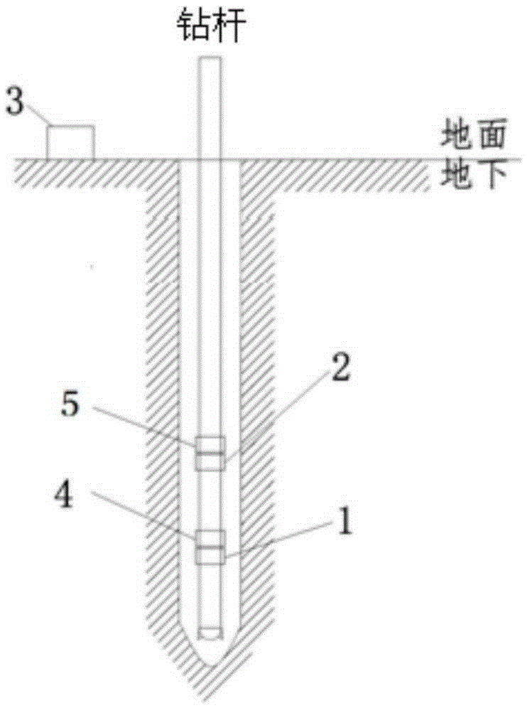
[0011] The gas intrusion early monitoring method involved in this embodiment is implemented using a gas intrusion early monitoring device. The lower pressure measuring device 1 and the short-distance wireless signal transmitter 4 and the upper pressure measuring device 2 are respectively installed on the downhole drill pipe according to the set spacing. And the downhole signal transmitter 5, the lower pressure measuring device 1 and the upper pressure measuring device 2 respectively measure the annulus fluid pressure at the location, and the short-distance wireless signal transmitter 4 measures the annulus fluid pressure at the location of the lower pressure measuring device 1. Transmitted to the upper pressure measuring device 2, the upper pressure measuring device 2 calculates the pressure difference and density of the annular fluid pressure between the lower pressure measuring device 1 and the upper pressure measuring device 2, and the upper pressure measuring device 2 can jud...


PUM


Abstract

The invention belongs to the technical field of monitoring methods, and relates to a gas cutting early stage monitoring method. The method is implemented through a gas cutting early stage monitoring device. A lower pressure meter and an upper pressure meter are installed on an underground drill rod according to a set interval, the annulus fluid pressure at the positions where the lower pressure meter and the upper pressure meter are located is measured and the annulus fluid density is further calculated. The installation distance between the lower pressure meter and the upper pressure meter can be adjusted, and the problem that the annulus fluid pressure between two close distance points cannot be measured due to the low underground fluid density is solved. The method does not depend on well logging during drilling equipment, production cost is lowered, applicability is improved, underground gas cutting is monitored through a conventional MWD or EMWD or ATWD in the oil and natural gas drilling process, and the purposes of early discovery, timely coping, avoiding of property and personnel losses are achieved. The technological process is simple, the principle is scientific and reasonable, operation is convenient, practicability is good, the using environment is friendly, universality is high, and the method is safe, reliable and easy to apply and popularize.

Description

Technical field: [0001] The invention belongs to the technical field of monitoring methods, and relates to an early gas invasion monitoring method. During oil and natural gas drilling, the occurrence of downhole gas invasion is monitored to realize the purpose of early detection, timely response, and avoiding property and personnel losses. Background technique: [0002] Gas invasion is a phenomenon in which the effective pressure at the bottom of the well decreases during the drilling process, which causes the gas in the formation to intrude into the wellbore; when drilling the gas layer, as the gas layer rock is broken, the gas contained in the rock pores invades the drilling fluid. When a large fracture or cave gas reservoir is reached, a large amount of replaceable gas may suddenly invade the drilling fluid. The gas in the gas layer continuously diffuses into the well through the drilling fluid. When the bottom hole pressure is lower than the formation pressure, the downhole po...

Claims


Application Information

Patent Timeline
Patent Type & Authority Applications(China)
IPC IPC(8): E21B47/10E21B47/117E21B47/06
Inventor 李志刚
Owner CHINA UNIV OF PETROLEUM (EAST CHINA)
Why Eureka
Try Eureka