Gas film cooling hole structure used for thin-walled hot end part of gas turbine engine

A technology of air film cooling and hot end components, which is applied in the cooling of engines, cooling of turbine/propulsion devices, engine components, etc., can solve the problems of reducing the jet flow of the cold air outlet, weakening the kidney-shaped vortex, and difficult to process and manufacture. , to reduce the processing difficulty, enhance the coverage effect, and increase the export area.

Active Publication Date: 2016-02-03
TSINGHUA UNIV
View PDF5 Cites 1 Cited by
  • Summary
  • Abstract
  • Description
  • Claims
  • Application Information

AI Technical Summary

Problems solved by technology

The traditional cylindrical air film hole forms a kidney-shaped vortex pair in the air film cooling flow field. This vortex structure draws the high-temperature mainstream into the cold air jet from both sides, causing the cold air to blow away from the cooling wall surface, resulting in a loss of cooling effect. Deterioration; while the traditional forming hole enlarges the area of ​​the hole exit, reduces the outlet jet flow of the cold air, thereby weakening the generation of the kidney-shaped vortex, and increases the lateral coverage of the cold air due to the enlarged outlet area, thus obtaining Compared with the cylindrical hole, the film cooling effect is better, but the traditional forming hole is still unable to actively generate the vortex structure of the flow field that is beneficial to the film cooling; then in order to construct the vortex structure of the flow field that is conducive to the film cooling, Some experts and scholars have combined two or more cylindrical holes into a film hole unit, such as double-jet holes, tripod holes, etc. It is difficult to get application under air space conditions and other deficiencies
In addition, as the hot-end components of gas turbines, such as combustion chambers and turbine blades, gradually begin to turn to the trend of thin-wall cooling, the thinning of the wall thickness has brought huge obstacles to the processing of complex-shaped film cooling holes such as forming holes. Make the forming hole processing can not be carried out smoothly

Method used


Image

  • Gas film cooling hole structure used for thin-walled hot end part of gas turbine engine
  • Gas film cooling hole structure used for thin-walled hot end part of gas turbine engine
  • Gas film cooling hole structure used for thin-walled hot end part of gas turbine engine

Examples


Embodiment Construction

[0015] Structure, principle and performance of the present invention are described below in conjunction with accompanying drawing:

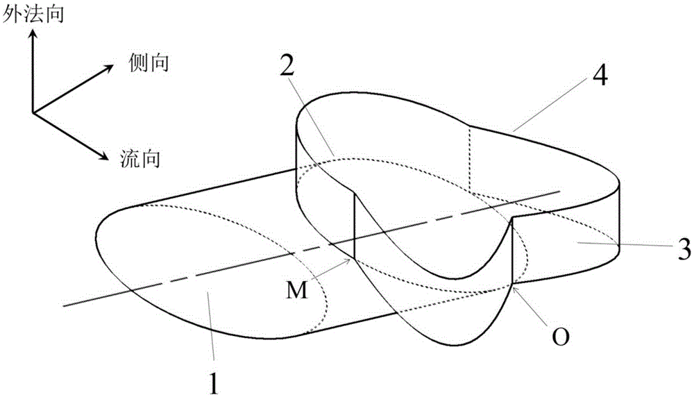
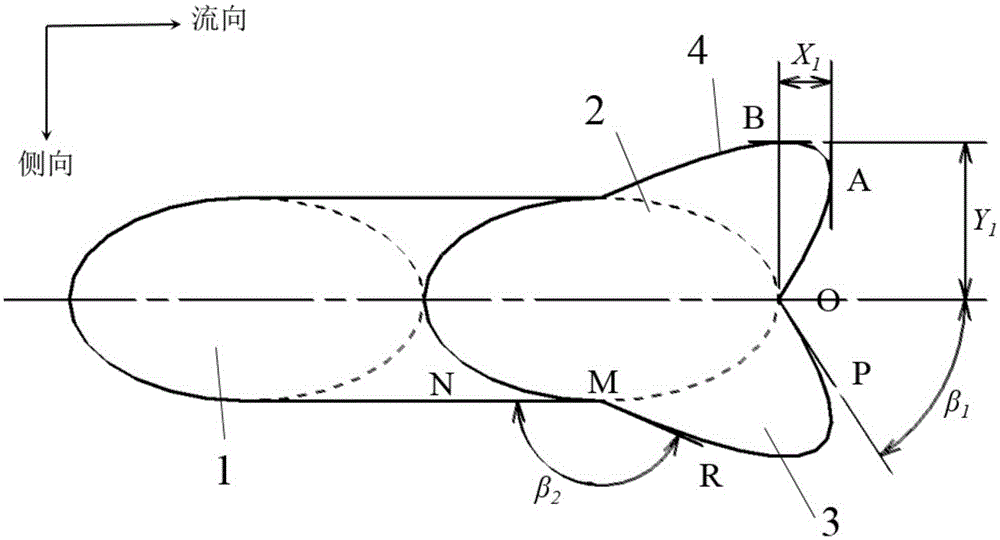
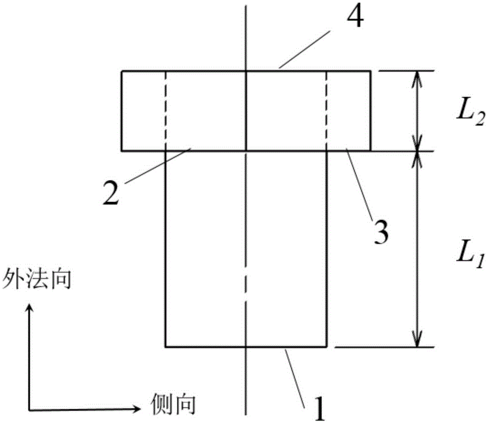
[0016] The present invention is a film cooling hole structure for thin-walled hot end parts of a gas turbine engine, and its basic geometric features are as follows: figure 1 , figure 2 with image 3 shown. The film cooling hole includes an inlet section 1 and a pit section 2. The inlet section is a cylindrical hole, and the pit section 2 is connected by a "heart-shaped" pit section 3 on the leeward side of the hole and a semi-cylindrical pit section 4 on the windward side of the hole. Formed, the pit section 2 starts from the center of the end of the inlet section 1 as the origin, stretches toward the windward side of the hole to form a semi-cylindrical pit section 4, and stretches toward the leeward side of the hole to form a "heart-shaped" pit section 3;" Heart-shaped "dimple section 3 and semi-cylindrical dimple section 4 take the center ...


PUM


Abstract

The invention discloses a gas film cooling hole structure used for a thin-walled hot end part of a gas turbine engine and belongs to the technical field of gas turbine engines. The gas film cooling hole comprises an inlet segment and a pit segment; the inlet segment is a cylindrical hole; the pit segment is formed by connecting a pit segment body shaped like a Chinese character 'xin' and located on the hole leeward with a semi-cylindrical pit segment body located on the hole windward face; starting from the tail end circle center, serving as an original point, of the inlet segment, the pit segment starts to expand to the hole windward face to form the semi-cylindrical pit segment body, and expand to the hole leeward to form the pit segment body shaped like the Chinese character 'xin'; and the pit segment body shaped like the Chinese character 'xin' and the semi-cylindrical pit segment body use an outlet cross section center point of the cylindrical hole as a demarcation point. The gas film cooling hole has the beneficial effects that the outlet area of the gas film cooling hole can be increased, the cold gas outlet momentum is reduced, and the cold gas covering effect is enhanced; and inverted-kidney-shaped vortexes are generated through the pit segment body shaped like the Chinese character 'xin' and located on the leeward of the pit segment, a flow field structure favorable for gas film cooling coverage is constructed, and the wall face can be better covered with cooling fluid.

Description

technical field [0001] The invention relates to a gas turbine engine, specifically including heavy-duty gas turbines for power generation, aeroengines, and ship gas turbines. Film cooling efficiency for high temperature components such as flats, combustion chambers, film cooling for all discrete hole forms, and for thin-walled hot end components. Background technique [0002] The operating temperature of modern gas turbine engines has exceeded the withstand temperature of metallic materials. As an efficient cooling method, film cooling is widely used in the cooling of high-temperature components of heavy-duty gas turbines, aero-engines and ship gas turbines. Film cooling is the jet flow of cooling gas from one or more discrete holes to form a gas film on the wall to protect the wall from being ablated by high temperature gas. In a gas turbine engine, the air used for cooling is generally compressed air extracted from the corresponding stage of the compressor. The efficienc...

Claims


Application Information

Patent Timeline
Patent Type & Authority Applications(China)
IPC IPC(8): F02C7/18
Inventor 蒋洪德任静李威宏
Owner TSINGHUA UNIV
Why Eureka
Try Eureka