
Gear combination transmission mechanism

A technology of transmission mechanism and gear combination, which is applied in the direction of transmission, belt/chain/gear, mechanical equipment, etc., can solve the problem that the direction and speed of the output shaft and the output shaft of the input shaft cannot be changed, and improve the applicable occasions and scope. Effect

Inactive Publication Date: 2016-02-03
ZHENGZHOU UNIV
View PDF7 Cites 2 Cited by
  • Summary
  • Abstract
  • Description
  • Claims
  • Application Information

AI Technical Summary

Problems solved by technology

[0004] The object of the present invention is to overcome the defect that the existing circular gear transmission mechanism is mainly for changing the transmission ratio between the output shaft and the input shaft, the direction and the speed of the output shaft cannot be changed, and to provide a gear combination transmission mechanism, which can be used in Under the same input conditions, the transmission direction, speed and reciprocating range of the output shaft can be changed, which can adapt to the institutional requirements and various changes of reciprocating and reciprocating ranges as well as speed adjustment movements.

Method used


Image

  • Gear combination transmission mechanism
  • Gear combination transmission mechanism
  • Gear combination transmission mechanism

Examples


Embodiment Construction

[0043] According to the following detailed description of specific embodiments of the present invention in conjunction with the accompanying drawings, those skilled in the art will be more aware of the above and other objects, advantages and features of the present invention.

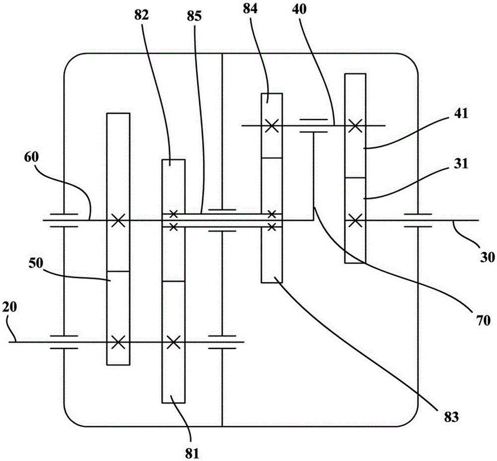
[0044] figure 1 It is a schematic structural diagram of a gear combination transmission mechanism according to an embodiment of the present invention. Such as figure 1 As shown, the embodiment of the present invention provides a gear combination transmission mechanism, which may include an input shaft 20 and an output shaft 30 . The input shaft 20 can be connected with the rotary motor, and the output shaft 30 is used to output motion satisfying motion requirements. Specifically, the gear combination transmission mechanism also includes a sun gear 31 , an intermediate shaft 40 , a planetary gear 41 and two transmission components. The sun gear 31 can be fixed to the output shaft 30 . The intermediat...


PUM


Abstract

The invention provides a gear combination transmission mechanism. The mechanism can comprise an input shaft and an output shaft and particularly comprises a sun wheel, a middle shaft, a planet wheel and two transmission assemblies. The sun wheel is fixed to the output shaft, and the middle shaft and the output shaft are arranged at an interval in parallel; the planet wheel is mounted on the middle shaft and meshed with the sun wheel; the two transmission assemblies are configured to enable rotation motion of the input shaft to be converted into the rotation motion of the middle shaft around the output shaft and rotation motion of the planet wheel around the middle shaft; and at least one transmission assembly comprises a non-circular gear pair composed of two meshed non-circular gears, and therefore the instantaneous transmission ratio between the output shaft and the input shaft is changed according to a curve. According to the gear combination transmission mechanism, the transmission direction, the speed and the back-and-forth amplitude of the output shaft can be changed, and the mechanism can be suitable for meeting the requirements and various changes of mechanisms with reciprocating and back-and-forth amplitudes and speed adjusting motion.

Description

technical field [0001] The invention relates to a mechanical transmission mechanism, in particular to a gear combination transmission mechanism. Background technique [0002] At present, the combined circular gear transmission mechanism is mainly designed to change the transmission ratio between the output shaft and the input shaft, and the direction of motion and the speed of the output shaft of this type of mechanism cannot be changed. And various complex motions, such as reciprocating motion, non-uniform motion, etc., are mostly realized by crank rocker mechanism, cam mechanism, combined mechanism, etc. Although this type of mechanism has achieved good results in application, there are still problems such as low transmission efficiency, poor motion stability, and complicated mechanism. The gear mechanism has always been the best choice in the transmission field due to its high efficiency, good stability, and simple structure. [0003] It is also an option in current act...

Claims


Application Information

Patent Timeline
Patent Type & Authority Applications(China)
IPC IPC(8): F16H37/04
CPCF16H37/042
Inventor 张瑞石宪章吴序堂孙嘉敏张帅李芳喇凯英
Owner ZHENGZHOU UNIV
Learn More