Laser drying box

A drying oven and laser technology, applied in drying, drying machine, heating device and other directions, can solve the problems of affecting drying efficiency and long heating time, and achieve the effect of improving drying efficiency, high drying efficiency and good drying effect.

Inactive Publication Date: 2016-02-03
NANJING HAIYUAN CHINESE HERBAL PIECES CO LTD
View PDF1 Cites 2 Cited by
  • Summary
  • Abstract
  • Description
  • Claims
  • Application Information

AI Technical Summary

Problems solved by technology

Although this drying oven solves the problem of uniform heating, it is not suitable for high-temperature heating because it still uses hot air pipe heating, which will cause the heating time to be too long and affect the drying efficiency

Method used


Image

  • Laser drying box

Examples


Embodiment

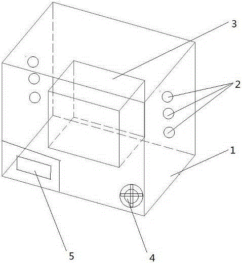
[0027] Such as figure 1 Shown, a kind of laser drying box comprises box body 1, laser transmitter 2 and laser receiving box 3; Described laser transmitter 2 is arranged on the inner wall of box body 1, and described laser receiving box 3 is located at Inside of box 1.

[0028] The drying box also includes a laser energy adjustment knob 4 connected to the laser emitter 2 , and the laser energy adjustment knob 4 is arranged on the box body 1 . The laser emitters 2 are equidistantly arranged on the inner wall of the box body 1 , and the emitting direction faces the laser receiving box 3 . The laser emitter 2 is arranged on the inner wall of the side of the box body 1 . The laser emitter 2 is arranged on the inner wall of the bottom and the top of the box body 1 . The outside of the box 1 is provided with a display screen 5 to display the pressure and temperature of the laser receiving box. The inside of the box 1 is provided with an exhaust pipe, one end of which is connected...


PUM


Abstract

The invention discloses a laser drying box, and belongs to the field of drying devices. The laser drying box comprises a box body, laser emitters and a laser receiving box. The laser emitters are arranged on the inner wall of the box body. The laser receiving box is arranged in the box body. The laser drying box is simple in structure and convenient to use. Materials are placed in the laser receiving box and can be rapidly dried through the high temperature generated by the laser emitters, the drying effect is good, the drying efficiency is high, and the production efficiency of enterprises is improved.

Description

technical field [0001] The invention relates to the field of drying equipment, in particular to a laser drying box. Background technique [0002] The solid products or semi-finished products obtained in the production process of pharmaceutical companies often contain too much water or organic solvents (moisture), and the excess moisture in the solid materials needs to be removed to prepare qualified products. The usual practice is to remove most of the moisture contained in the solid material by mechanical means, and then use the medicine drying equipment to remove the moisture that is not easy to remove, so that the solid material can meet the needs of continuous production and use. [0003] In the field of pharmaceutical production, the common drying equipment is a drying oven. The existing drying oven is usually equipped with a heating tube inside the box, and is heated by the heating tube. However, this type of heat pipe heating takes a long time to preheat, and the eff...

Claims


Application Information

Patent Timeline
Patent Type & Authority Applications(China)
IPC IPC(8): F26B23/04
Inventor 陈林伟秦昆明金俊杰王彬陈丹妮张彦南郑艳萍黄雨婷范孟雪
Owner NANJING HAIYUAN CHINESE HERBAL PIECES CO LTD
Why Eureka
Try Eureka