Car seat simulative vibration experiment table

A technology of car seats and test benches, which is applied in the field of mechanical vibration tables, can solve problems such as high cost and difficult frequency adjustment, and achieve the effect of improving power requirements and control accuracy

Inactive Publication Date: 2016-02-03
GUANGXI UNIV
View PDF8 Cites 9 Cited by
  • Summary
  • Abstract
  • Description
  • Claims
  • Application Information

AI Technical Summary

Problems solved by technology

[0004] In order to solve the problems of mechanical car seat simulation vibration test bench amplitude, frequency adjustment difficulty, high cost, etc., the technical solution adopted in the present invention is: a car seat simulation vibration test bench, which is characterized in that it consists of a first servo motor, a second A constant speed motor, a second constant speed motor, a double drive crank slider mechanism, a second servo motor, a vertical guide mechanism, a horizontal drive motor, a seat system, a horizontal guide mechanism, a second drive shaft, a first drive shaft, a long The first servo motor and the second constant speed motor are the two power sources of the double drive crank slider mechanism, the first servo motor drives the second drive shaft through the long shaft, and the second constant speed motor The first drive shaft is driven by a high-speed motor, and the vertical vibration motion is transmitted to the vibration table under the action of the vertical guide mechanism; the horizontal drive motor generates horizontal vibration motion to the vibration table through the eccentric wheel mechanism and the horizontal guide mechanism; the seat system installation On the vibrating table, the vibrating table can transmit the received vertical vibration motion and horizontal vibration motion to the seat system

Method used


Image

  • Car seat simulative vibration experiment table
  • Car seat simulative vibration experiment table

Examples


Embodiment Construction

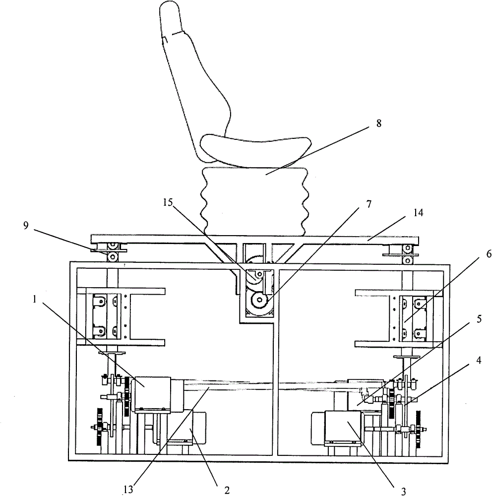
[0008] The present invention will be further described below in conjunction with the accompanying drawings and embodiments.

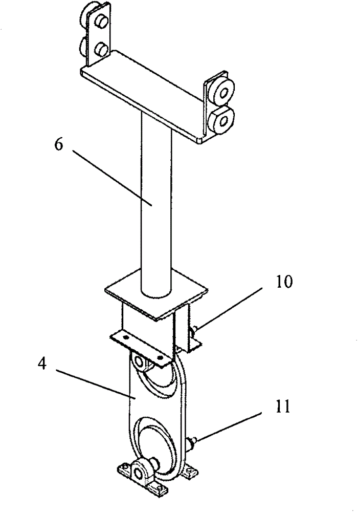
[0009] A car seat simulated vibration test bench, consisting of a first servo motor (1), a first constant speed motor (2), a second constant speed motor (3), a double-drive crank slider mechanism (4), a second servo Motor (5), vertical guide mechanism (6), horizontal drive motor (7), seat system (8), horizontal guide mechanism (9), second drive shaft (10), first drive shaft (11), long shaft (13), vibration table (14), and eccentric wheel mechanism (15); wherein the first servo motor (1) drives the second drive shaft (10) through the long shaft (13), and the second constant speed motor (3) Driving the first drive shaft (11), the first servo motor (1) and the second constant-speed motor (3) are the two power sources of the double-drive slider crank mechanism (4), and they function as the vertical guide mechanism (6). The vertical excitation motion is tra...


PUM


Abstract

A car seat simulative vibration experiment table includes two vertical vibration mechanisms and one horizontal vibration mechanism, and can generate the vibration motion in the vertical direction. The car seat simulative vibration experiment table adopts a combination drive mode of a normal speed motor drive and a servo motor drive. The car seat simulative vibration experiment table controls the revolving speeds and initial phase differences of two driving motors by utilizing a dual drive slider-crank mechanism of the vertical vibration mechanism so as to realize the on-line stepless amplitude adjustment and frequency adjustment of the vertical vibration motion. The horizontal driving motor generates the horizontal vibration motion to the vibration table face through an eccentric wheel mechanism and a horizontal guide mechanism so that the car seat simulative vibration experiment table has three freedom degrees of vertical vibration motion, horizontal vibration motion and horizontal swinging. The car seat simulative vibration experiment table solves problems that the amplitude and frequency of an existing mechanical type car seat simulative vibration experiment table are difficult to adjust and the existing mechanical type car seat simulative vibration experiment table is high in cost. The car seat simulative vibration experiment table provided by the invention can be widely provided for car seat manufacturers to perform car seat vibration experiments.

Description

Technical field: [0001] The invention relates to an automobile seat simulation vibration test platform, which belongs to the field of mechanical vibration platforms. Background technique: [0002] The traditional mechanical car seat vibration table is cheap, but the phase control accuracy between the excitation units is low, and the amplitude adjustment is difficult. However, with the development of technology, the control accuracy of the mechanical car seat vibration table has been significantly improved in recent years. A new type of mechanical vibration test bench with a servo motor as the power source has been developed abroad. The servo motor is transformed into a reciprocating linear motion of the platform through a ball screw. The profiling boss is fixed on the platform and the contour shape of the profiling boss can be changed. Change the amplitude and frequency of the passive rod (vibration output shaft). However, the servo motor needs to rotate forward and reverse...

Claims


Application Information

Patent Timeline
Patent Type & Authority Applications(China)
IPC IPC(8): G01M7/06
Inventor 张铁异周晓蓉曾燕斌庞汉礼黄清
Owner GUANGXI UNIV
Why Eureka
Try Eureka