
Power supply plant grounding resistance measuring device and control method

A technology of grounding resistance and measuring device, which is applied in impedance measurement and other directions, can solve the problems of increasing equipment weight, large grounding resistance, and interference with measurement results, and achieves the effect of convenient measurement and fast measurement speed.

Inactive Publication Date: 2016-02-03
TIANJIN BAILI ELECTRIC CO LTD
View PDF5 Cites 0 Cited by
  • Summary
  • Abstract
  • Description
  • Claims
  • Application Information

AI Technical Summary

Problems solved by technology

For example, on July 16, 2003, thunderstorms occurred in most areas of Shuangyashan. Due to the large grounding resistance in the grounding system of the State Taxation Bureau of the power plant, part of the information system of the bureau was attacked by lightning, causing huge losses to computers and communication equipment.
[0003] At present, most grounding resistance measuring devices are pointer-type, and the value is read through the graduation value of the dial, which is accurate to the percent; the internal power supply is provided by a built-in hand generator, which increases the weight of the equipment and prolongs the measurement time. During the power generation process Resulting electromagnetic fluctuations can interfere with measurement results

Method used


Image

  • Power supply plant grounding resistance measuring device and control method
  • Power supply plant grounding resistance measuring device and control method

Examples


Embodiment Construction

[0020] In order to further understand the content, characteristics and effects of the present invention, the following examples are given, and detailed descriptions are as follows in conjunction with the accompanying drawings:

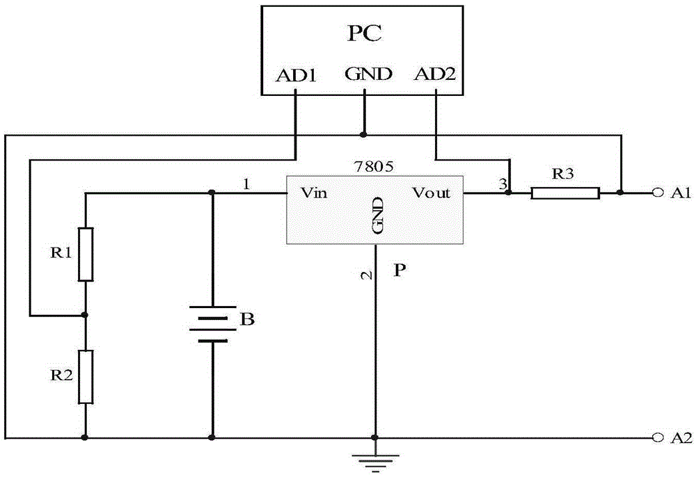
[0021] like figure 1 As shown, the left side of the positive electrode of the lithium battery B that provides power for the device flows to the negative electrode of the lithium battery B through the power voltage dividing resistor R1 and the sampling resistor R2, and the two ends of the sampling resistor R2 are respectively connected to the AD1 and GND ports of the embedded touch PC. The collected voltage signal is used as the basis to reflect the power of lithium battery B, and its internal processor can calculate the real-time voltage of B according to the programmed program; the right side of the positive electrode of lithium battery B is first passed through the 7805 voltage regulator P ( Generate port 1 of DC5V), and then port 2 of voltage regula...


PUM


Abstract

The invention relates to a power supply plant grounding resistance measuring device and a control method. The power supply plant grounding resistance measuring device comprises a power supply part, an embedded touch control PC and a voltage collection part. The power supply part is a chargeable battery (B). The voltage collection part comprises resistors R1, R2 and R3 and a voltage stabilizer. An anode of the chargeable batter is connected with one end of the resistor R1 and a port Vin of the voltage stabilizer. A cathode of the chargeable battery is connected with one end of the resistor R2, a grounding end of the voltage stabilizer and a terminal A2. The other ends of the resistors R1 and R2 are mutually connected and are connected with an I / O port of the embedded touch control PC. A port Vout of the voltage stabilizer is connected with the other I / O port of the embedded touch control PC and one end of the resistor R3. The other end of the resistor R3 is connected with a terminal A and the cathode of the chargeable battery. A grouding end of the embedded touch control PC is connected with the cathode of the chargeable battery. The power supply plant grounding resistance measuring device has the advantages that a specific measurement result can be read because of a digital display function, the measurement result can be accurate to an extreme position, the measurement speed is high, the power supply plant grounding resistance measuring device is chargeable and portable, long-distance measurement can be performed, a measurement result self-checking function is provided, and the measurement is more convenient and rapid.

Description

technical field [0001] The invention belongs to a detection device for electrical components, in particular to a ground resistance measurement device and control method for a power supply plant. Background technique [0002] In recent years, some substations in my country have caused accidents due to lightning strikes, most of which are due to the unqualified grounding resistance of the grounding grid. The grounding grid plays the role of working grounding and protective grounding. At the same time, whether the grounding resistance of the grounding system is qualified is directly related to the property safety of the substation. and staff safety. For example, on July 16, 2003, thunderstorms occurred in most areas of Shuangyashan. Due to the large grounding resistance in the grounding system of the State Taxation Bureau of the power plant, part of the information system of the bureau was attacked by lightning, causing huge losses to computers and communication equipment. . ...

Claims


Application Information

Patent Timeline
IPC IPC(8): G01R27/18
Inventor 范钦赞陈浩李津莲王铁镰樊亚辉
Owner TIANJIN BAILI ELECTRIC CO LTD
Learn More