Feed structure of air integrated waveguide

An integrated waveguide and feed technology, applied in the direction of the structure of the radiation element

Active Publication Date: 2016-02-03
HARBIN INST OF TECH
View PDF7 Cites 1 Cited by
  • Summary
  • Abstract
  • Description
  • Claims
  • Application Information

AI Technical Summary

Problems solved by technology

[0003] In order to solve the contradiction between the miniaturization and low loss of the existing ultra-thin waveguide, the present invention proposes a feeding structure of the air-integrated waveguide

Method used


Image

  • Feed structure of air integrated waveguide
  • Feed structure of air integrated waveguide
  • Feed structure of air integrated waveguide

Examples


specific Embodiment approach 1

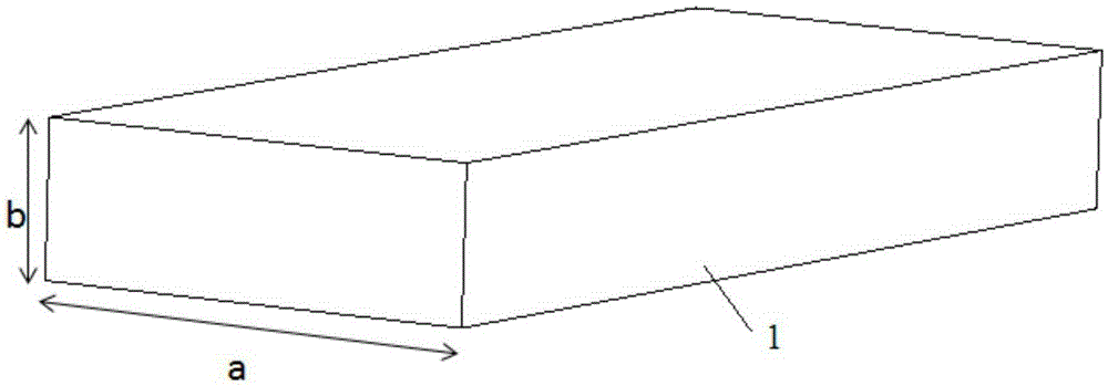
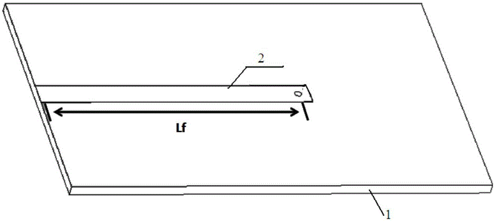
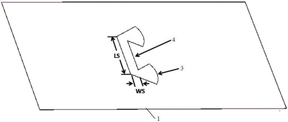
[0019] Specific implementation mode 1. Combination Figure 1 to Figure 5 Describe this embodiment mode, the feeding structure of an air-integrated waveguide described in this embodiment mode, which includes a rectangular waveguide plate 1, a microstrip line 2, a fan-shaped area 3, a coupling slot 4, a waveguide slot 5, a feed slot 6 and metal plate 7;

[0020] The upper surface of the rectangular waveguide plate 1 is engraved with a waveguide groove 5 and a feed groove 6, the depth of the feed groove is greater than the depth of the waveguide groove; the waveguide groove 5 is rectangular, and the feed groove 6 is arranged adjacent to the waveguide groove 5; Above the waveguide groove 5 and the feeding groove 6, and maintain electrical connection with the rectangular waveguide plate 1; the metal plate 7 forms the waveguide cavity and the feeding cavity with the waveguide groove 5 and the feeding groove 6; the waveguide cavity and the feeding cavity A feed structure is formed; ...


PUM

PropertyMeasurementUnit
Lengthaaaaaaaaaa

Abstract

A feed structure of an air integrated waveguide relates to a feed structure of a waveguide and solves the conflict between miniaturization and low loss of ultrathin waveguides in the prior art. A waveguide slot and a feed slot are carved in the upper surface of a rectangular waveguide plate. The depth of the feed slot is greater than that of the waveguide slot, and the feed slot is arranged near the waveguide slot. A metal plate covers the waveguide slot and the feed slot from the top and is electrically connected with the rectangular waveguide plate. The metal plate, the waveguide slot and the feed slot form a waveguide chamber and a feed chamber. A coupling slit is carved in the metal plate above the feed chamber. The coupling slit is a rectangular through hole. A fan-shaped through hole is carved at each of two ends of the coupling slit. A microstrip line is arranged above the rectangular waveguide plate. A starting end of the microstrip line is aligned with a short side of the rectangular waveguide plate, a tail end of the microstrip line is above the waveguide chamber, and the body of the microstrip line is above the coupling slit. The feed structure is suitable for being used as an electromagnetic wave feed structure of a waveguide.

Description

technical field [0001] The invention relates to a waveguide feeding structure. Background technique [0002] With the development of modern communication systems, the integration of electronic equipment is getting higher and higher. As a microwave signal transmission device, the metal waveguide has the advantages of firm structure, low loss and large power capacity. However, the existing rectangular waveguides are generally relatively large, and in order to improve the integration of wireless communication devices, the size of the waveguides needs to be reduced. People once proposed a dielectric integrated waveguide (SIW) method, which can be used to manufacture a very thin dielectric waveguide. However, the dielectric integrated waveguide is filled with dielectric material, causing it to have greater losses than air waveguides. As for the air waveguide, when its air cavity is very thin (the thickness of the waveguide is only a few hundred microns or even tens of microns,...

Claims


Application Information

Patent Timeline
IPC IPC(8): H01Q1/38H01Q1/36
Inventor 孟繁义
Owner HARBIN INST OF TECH
Why Eureka
Try Eureka