Surge current suppression circuit

A technology for suppressing circuits and surge currents, applied to electrical components, output power conversion devices, etc., can solve problems such as short service life of relays, poor suppression effect, loss of surge suppression ability, etc., and achieve surge current suppression Effect

Active Publication Date: 2016-02-03
MEANWELL GUANGZHOU ELECTRONICS
View PDF6 Cites 8 Cited by
  • Summary
  • Abstract
  • Description
  • Claims
  • Application Information

AI Technical Summary

Problems solved by technology

In these methods, the contradiction between the surge suppression effect and the device's own loss is difficult to reconcile, so the suppression effect is not good
Each specific method has its own problems that are difficult to overcome: the resistance of the thermistor becomes very large in a low temperature environment, causing difficulty in starting up, and the resistance value becomes small at high temperatures, losing the ability to suppress surges; the use of relays Short life, prone to failure after multiple boots

Method used


Image

  • Surge current suppression circuit

Examples


Embodiment 1

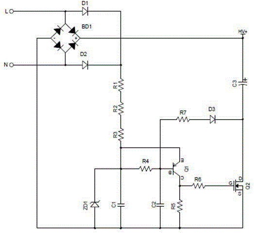
[0020] like figure 1 As shown, a surge current suppression circuit includes a rectifier bridge BD1, diodes D1-D3, resistors R1-R7, capacitors C1-C3, a voltage regulator tube ZD1, a transistor Q1, and a field effect transistor Q2; the rectifier bridge BD1 includes four Interconnected diodes, where two diodes are connected with a common cathode, and the other two diodes are connected with a common anode, the cathodes of the two diodes connected with the common anode are connected with the anodes of the two diodes connected with the common cathode, and two groups of two diodes connected with different poles The connection point between the diodes is connected between the neutral line and the live line of the commercial power; the anode of the diode D1 is connected to the live line, the cathode of the diode D1 is connected to one end of the resistor R1, and the other end of the resistor R1 is connected to one end of the resistor R2. The other end of the resistor R2 is connected to...


PUM


Abstract

The invention provides a surge current suppression circuit. After the suppression circuit is electrified, an alternating-current power supply charges a C1 via a D1, a D2, an R1, an R2 and an R3. The voltage of the C1 is stabilized to be the clamping voltage of a voltage-regulator tube ZD1. The positive-end level of the C3 is the input voltage after rectification, the waveform is the sine half-wave and the C3 does not have charging access. The voltage of the C3 is 0, thus, the negative end level of the C3 changes along with the positive-end voltage and change conditions of the power voltage is directly reflected. Before the power voltage is lower than the Q1 operating voltage, a Q1 and a Q2 are kept in the turned-off state. When the power voltage changes to be lower than the Q1 operating voltage, the power level state is reflected by the negative-end level of the C3 and then the Q1 is conductive. Current flows into the grid electrode of the Q2 via the Q1 and an R6 from the C1, so level of the Q2 is increased and exceeds the open threshold voltage, and the Q2 is conductive. When the power voltage charges the C3 via the Q2, the instantaneous value of the power voltage is quite low and the surge current can be suppressed.

Description

technical field [0001] The invention relates to the field of power supply protection circuits, and more specifically, to a surge current suppression circuit. Background technique [0002] Switching power supply equipment is a capacitive load for the power grid. When the device is connected to the grid, it is in a short-circuit state and absorbs a huge current from the grid, which is called the inrush current (Inrush current). Switching power supply equipment has caused a threat, if it is not suppressed, it will cause abnormal or even damage to the equipment. [0003] At present, the commonly used suppression method is to connect impedance devices in series in the circuit, such as power resistors, thermistors, and thermistors with relays. In these methods, the contradiction between the surge suppression effect and the device's own loss is difficult to reconcile, so the suppression effect is not good. Each specific method has its own problems that are difficult to overcome: ...

Claims


Application Information

Patent Timeline
IPC IPC(8): H02M1/32
Inventor 王飞隆李楠
Owner MEANWELL GUANGZHOU ELECTRONICS
Why Eureka
Try Eureka