
Robust beamforming method with resistance to array system errors

A system error and robust technology, applied in the transmission system, radio transmission system, diversity/multi-antenna system, etc., can solve the problems of estimation deviation, existence error, and rapid decline of output SINR, etc., to achieve reduced sensitivity and strong robustness , the effect of improving robustness

Inactive Publication Date: 2016-02-03
HARBIN ENG UNIV
View PDF5 Cites 20 Cited by
  • Summary
  • Abstract
  • Description
  • Claims
  • Application Information

AI Technical Summary

Problems solved by technology

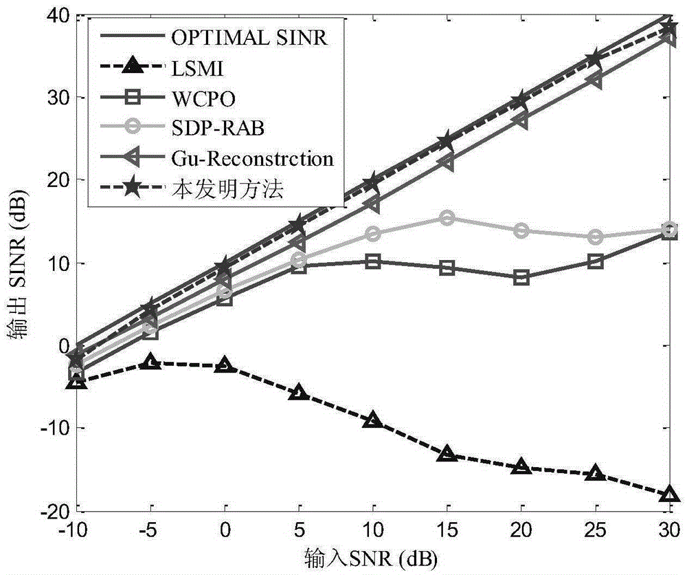
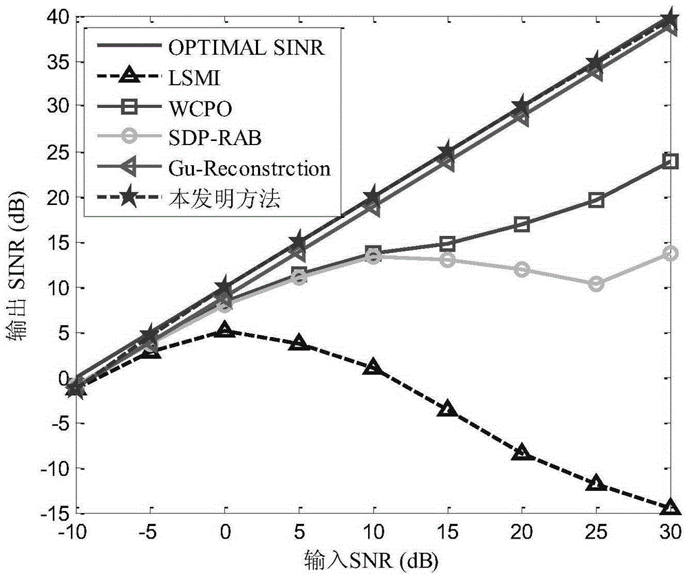
However, when the expected signal exists in the training signal, even if there is no error in the array steering vector, the performance of the LSMI algorithm and the WCPO algorithm is far lower than the ideal situation in the case of high SNR. In order to overcome this shortcoming, Y.Gu et al. proposed A robust beamforming method based on interference-plus-noise covariance matrix estimation (Gu, Y.J., and Leshem, A. Robust adaptive beamforming based on interference covariance matrix reconstruction and steering vector estimation. IEEE Transactions on Signal Processing, 2012, 60, (7), pp.3881–3885), which utilizes the Capon spectrum to reconstruct the interference plus noise covariance matrix without knowing the amount of interference. This method is extremely robust to the expected signal DOA estimation deviation, wavefront disturbance distortion, and steering vector mismatch caused by local phase scattering. The output SINR It can be close to the theoretical optimal value, which is the best robust beamforming method at present, but the disadvantage is that when the array manifold error occurs at low input signal-to-noise ratio, the output SINR will drop rapidly due to the error in the estimated covariance matrix

Method used


Image

  • Robust beamforming method with resistance to array system errors
  • Robust beamforming method with resistance to array system errors
  • Robust beamforming method with resistance to array system errors

Examples


Embodiment Construction

[0034] The present invention will be described in further detail below in conjunction with the accompanying drawings.

[0035] The purpose of the present invention is to provide a robust beamforming method capable of improving the anti-interference performance of adaptive antenna beamforming.

[0036] The purpose of the present invention is achieved like this:

[0037] The present invention comprises the steps:

[0038] (1) Construct the sampling covariance matrix of the data received by the array antenna:

[0039] (2 pairs Perform eigendecomposition: R ^ = Σ i = 1 N μ i υ ‾ i υ ‾ i H , i = 1 , 2 ...


PUM


Abstract

The invention discloses a robust beamforming method with resistance to array system errors. The method comprises the following steps: first, carrying out eigen-decomposition of a sampled data covariance matrix received by an array antenna; estimating an eigenvector corresponding to a desired signal according to the correlation between the steering vector of the desired signal and the eigenvector corresponding to the desired signal, so as to further remove the eigenvector corresponding to the desired signal out of the covariance matrix; performing weighted combination to a subspace (formed by the rest of eigenvectors) and an interference plus noise covariance matrix estimated by Capon spectrum to obtain an interference plus noise covariance matrix used in the beamforming method disclosed by the invention; and carrying out a quadratically constrained quadratic optimization algorithm to obtain the corrected steering vector of the desired signal. The robust beamforming method provided by the invention has the advantages of effectively avoiding performance reduction caused by array system errors and greatly improving the robustness of a beamformer; compared with the most of current robust beamforming methods, the robust beamforming method provided by the invention is capable of getting closer to a theoretical output SINR (signal to interference plus noise ratio) and has better output performance.

Description

technical field [0001] The invention belongs to the field of adaptive array antenna control, in particular to a robust beam forming method against array system errors. Background technique [0002] Adaptive beamforming technology can adaptively form nulls in the direction of spatial interference, effectively suppress spatial interference and noise, and improve the output signal-to-interference-noise ratio (SINR). It is widely used in radar, sonar, mobile communication, radio astronomy and other fields . Commonly used beamformers such as Capon beamformers are based on the fact that the array is accurately known to the steering vector of the desired signal. In practical applications, when there are signal wavefront disturbance distortion, local coherent scattering, array manifold errors, etc. When the array does not match the steering vector estimation of the desired signal, the adaptive beamformer will mistake the actual desired signal for interference, and form a null trap ...

Claims


Application Information

Patent Timeline
IPC IPC(8): H04B7/06
CPCH04B7/0617
Inventor 李文兴毛晓军李思毛云龙李迎松
Owner HARBIN ENG UNIV
Learn More