
Mechanical device and assembling method for automatic square ball valve assembling system

A technology of automatic assembly and mechanical device, applied in assembly machines, by detecting the appearance of fluid at the leak point, metal processing equipment, etc., it can solve the problem of difficulty in ensuring product quality stability and uniformity, square valve assembly and inflation process dispersion, Assembly quality skills, experience influence and other issues, to achieve the effect of saving assembly labor, achieving uniformity, and reducing labor intensity

Inactive Publication Date: 2016-02-10
CHINA UNIV OF MINING & TECH
View PDF5 Cites 16 Cited by
  • Summary
  • Abstract
  • Description
  • Claims
  • Application Information

AI Technical Summary

Problems solved by technology

It can be seen that the installation process of the square ball valve includes two processes of installation and inflation, both of which are completed manually. There are the following deficiencies in the installation process: 1. The assembly and inflation process of the square valve is scattered, which affects the production cycle of the entire product; 2. , The assembly and inflation process of the shaped valve are all manual operations, the assembly efficiency is low, and the labor intensity is high; 3. The assembly quality of the product is affected by the skills and experience of the workers, and it is difficult to guarantee the stability and uniformity of the product quality

Method used


Image

  • Mechanical device and assembling method for automatic square ball valve assembling system
  • Mechanical device and assembling method for automatic square ball valve assembling system
  • Mechanical device and assembling method for automatic square ball valve assembling system

Examples


Embodiment Construction

[0024] The present invention will be further explained below in conjunction with the accompanying drawings.

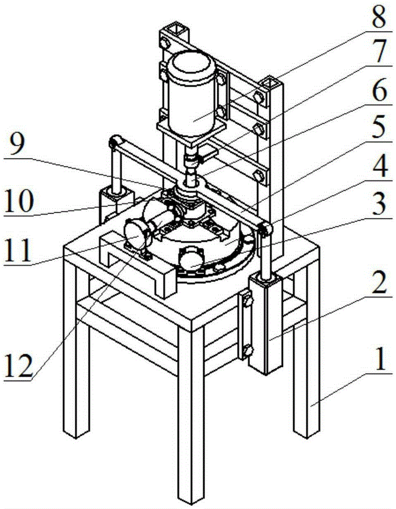
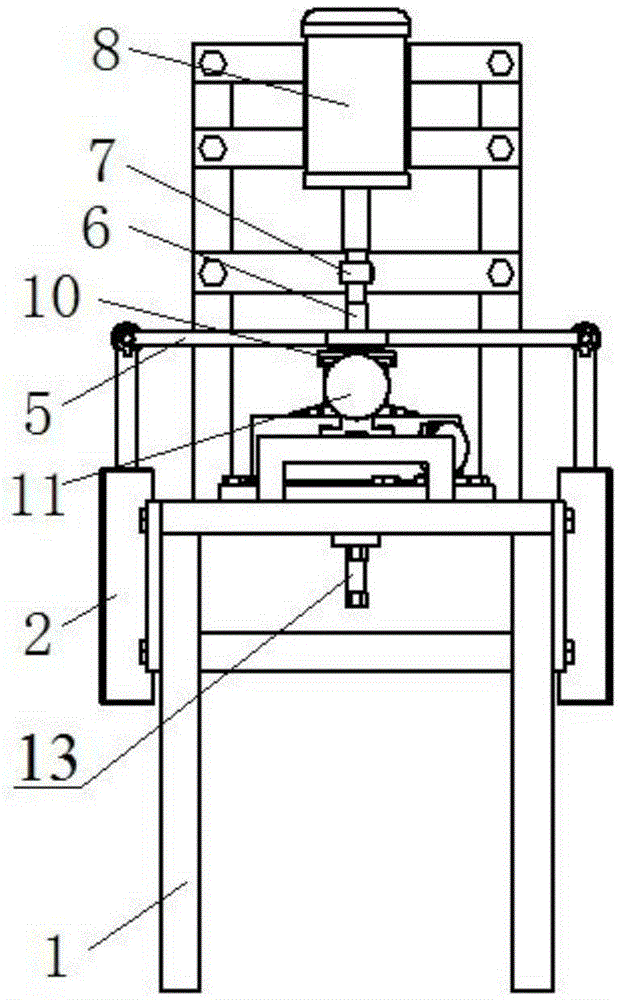
[0025] Such as Figures 1 to 7 As shown, a mechanical device of a square ball valve automatic assembly system includes a cylinder 2, an air motor one 3, a four-jaw chuck 4, a cylinder pressure plate 5, a motor 8, a rubber pad 10, an air motor two 11, a transmission sleeve 12 and a pneumatic Check valve 13.

[0026] The four-jaw chuck 4 is connected with the air motor one 3. During the clamping and dismounting process, the four-jaw chuck 4 is driven by the air motor one 3. A rubber pad 10 is arranged above the four-jaw chuck 4. The lower surface of the rubber pad 10 There is a profile protrusion matching the profile hole of the valve cover 904, the cylinder pressure plate 5 is set above the rubber pad 10, the motor 8 is connected with the top of the main drive connector 6 through the coupling 7, and the coupling 7 is provided with Torque sensor, the bottom of the main...


PUM


Abstract

The invention discloses a mechanical device and an assembling method for an automatic square ball valve assembling system. The mechanical device comprises a four-jaw chuck. The four-jaw chuck is connected with a first pneumatic motor, a rubber pad is arranged above the four-jaw chuck, and an air cylinder pressing plate is arranged above the rubber pad; an electric machine is connected with a main transmission connector through a coupling, and the main transmission connector penetrates through the air cylinder pressing plate and is connected with the rubber pad; an air cylinder and a second pneumatic motor are arranged on the side of the four-jaw chuck, the air cylinder is connected with the air cylinder pressing plate, the second pneumatic motor is connected with a transmission sleeve end, and a pneumatic one-way valve is arranged below the four-jaw chuck. The assembling method for the automatic square ball valve assembling system comprises the four steps of valve body clamping, valve cover tightening, valve element inflation and disassembling after assembling is finished. According to the mechanical device and the assembling method for the automatic square ball valve assembling system, integration of the procedures of automatic square ball valve assembling and automatic inflation is achieved, so that the assembling efficiency of a square ball valve and the production quality of a product are improved, and the labor intensity of a worker is reduced.

Description

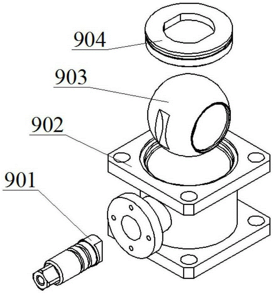
technical field [0001] The invention relates to a mechanical device and an assembly method of an automatic assembly system for a square ball valve. Background technique [0002] Square ball valves are widely used in the petroleum industry because of their simple structure and reliable performance. The structure of square ball valve mainly includes valve body, valve core, valve cover, valve knob and sealing ring. During the assembly process of the square ball valve, the tightness of the bonnet installation is very important to the assembly quality of the square ball valve. When the valve cover is installed loosely, the seal of the square ball valve does not bear a certain installation pre-tightening force, resulting in oil leakage during the working process; if the valve cover is installed too tightly, the installation pre-tightening force is too large, and the opening and closing of the valve is very Difficult, at the same time, the damage to the seal is also very large. ...

Claims


Application Information

Patent Timeline
Patent Type & Authority Applications(China)
IPC IPC(8): B23P21/00G01M3/04
CPCB23P21/002G01M3/04
Inventor 程延海杨明郑彤周建云曹帅潘家保崔然
Owner CHINA UNIV OF MINING & TECH
Learn More