

Double arm robot
A robot and two-arm technology, applied in the direction of robots, instruments, manipulators, etc., can solve problems such as complex structures and achieve the effect of improving work efficiency
- Summary
- Abstract
- Description
- Claims
- Application Information
AI Technical Summary
Problems solved by technology
Method used
Image

Examples
no. 1 approach
[0072] B1. The structure of the robot:
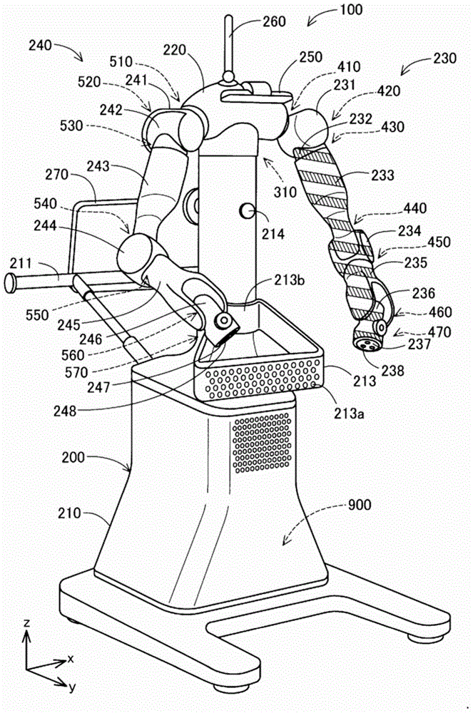
[0073] figure 1 It is a perspective view showing the robot 100 as the first embodiment of the present invention. The robot 100 includes a robot main body 200 and a robot control device 900 (also referred to as a “control unit 900 ”) that controls the operation of the robot main body 200 .
[0074] The robot main body 200 is a dual-arm robot, which has: a base (base) 210; a torso 220 connected to the base 210; a first multi-joint arm (also referred to simply as " A first arm") 230 and a second multi-joint arm (also simply referred to as "second arm") 240 . In addition, the robot main body 200 has: a stereo camera 250 disposed on the front of the torso 220; hand cameras (not shown) respectively disposed on the first multi-joint arm 230 and the second multi-joint arm 240; signal lights disposed on the torso 220 260 ; and a display 270 provided on the back side of the torso 220 .
[0075] The base 210 is provided with: a plurality of wh...
no. 2 approach
[0140] Figure 11 It is a perspective view showing a robot 100X as a second embodiment of the present invention. The robot 100X is other than the robot 100 of the first embodiment ( figure 1 ), that is, the first multi-joint arm 230 is the same as the robot 100 of the first embodiment except that the first multi-joint arm 230X is formed as the first multi-joint arm 230X.
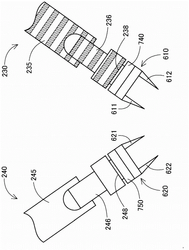
[0141] The first multi-joint arm 230X is the same as the first multi-joint arm 230, and has a first shoulder joint mechanism 410X, a first shoulder 231X, a second shoulder joint mechanism 420X, a second shoulder 232X, an upper arm Twist mechanism 430X, upper arm 233X, elbow joint mechanism 440X, first forearm 234X, forearm twist mechanism 450X, second forearm 235X, wrist joint mechanism 460X, wrist 236X, wrist twist mechanism 470X, and link 237X. Moreover, a hand operation device mounting part 238X is provided on the connecting part 237X, such as figure 2 As shown, the first hand manipulation device 610 ...
example 2
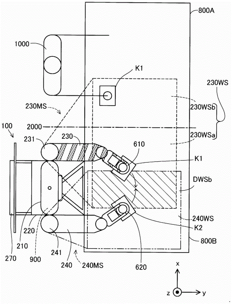
[0149] The robot 100X of the above-mentioned second embodiment ( Figure 11 ), as an example in which the structures of the first multi-joint arm 230X and the second multi-joint arm 240 are different, the case where the first multi-joint arm 230X is made thinner than the second multi-joint arm 240 is described. However, the difference in the structure of the first multi-joint arm 230X and the second multi-joint arm 240 is not limited to the thickness of the arms, and can be exemplified by the length of the arm, the thickness of the arm, the surface shape of the arm, the number of joints of the arm, At least one of various structural differences such as the movable angle of the joint, the plasticity or flexibility of the arm, the drive mechanism that drives the arm, and the motor included in the drive mechanism. That is, in order to improve the visibility of the first multi-joint arm 230X and draw the attention of the operator 1000 to the first multi-joint arm 230X, as long as ...
PUM
 Abstract
Description
Claims
Application Information