Electromagnetic pile driver

An electromagnetic pile driver, electromagnet technology, applied in the direction of sheet pile wall, building, foundation structure engineering, etc.

Inactive Publication Date: 2016-02-10
江苏易琥珀智能科技有限公司
View PDF11 Cites 7 Cited by
  • Summary
  • Abstract
  • Description
  • Claims
  • Application Information

AI Technical Summary

Problems solved by technology

Even so, pile drivers powered by petroleum energy

Method used


Image

  • Electromagnetic pile driver
  • Electromagnetic pile driver
  • Electromagnetic pile driver

Examples


Embodiment Construction

[0019] The present invention will be specifically introduced below in conjunction with the accompanying drawings and specific embodiments.

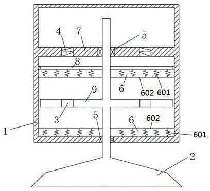
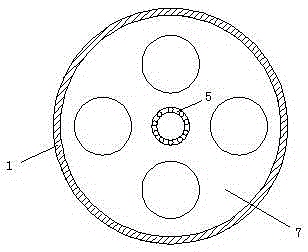
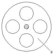
[0020] An electromagnetic pile driver, comprising: a fixed disk 7, an electromagnet 4 placed in the fixed disk 7, a moving disk 9, a closed coil 3 arranged on the moving disk 9 and corresponding to the electromagnet 4, formed on Electromagnetic hammer 2 on the moving disk 9. When the electromagnet 4 in the fixed disc 7 is passed to the alternating current of the set frequency, the magnetic poles and the magnetic field size of the electromagnet 4 in the fixed disc 7 will be periodic changes, and the closure in the movable disc 9 will The coil 3 will change the magnetic flux according to the change of the magnetic field of the electromagnet 4 in the fixed disk 7. According to Lenz's law, a circular current will be generated in the coil to form a magnetic field to hinder this change. When the magnetic field of the electromagnet 4 is strengt...


PUM


Abstract

The invention discloses an electromagnetic pile driver which comprises a fixed disc, electromagnets arranged in the fixed disc, a movable disc, closed coils and an electromagnetic hammer formed on the movable disc, wherein the closed coils are arranged on the movable disc and correspond to the electromagnets. Electric energy is adopted as the energy source by the pile driver, the electromagnets are arranged in the fixed disc, the closed coils are arranged in the movable disc, the electromagnetic hammer is connected to the movable disc, and the intensity of the electromagnets is changed according to the Lenz law to achieve piston movement of the movable disc, so that precise control over the pile driving force and frequency is achieved; meanwhile, energy is saved, emission is reduced, and noise is lowered.

Description

technical field [0001] The invention relates to a pile driving device, in particular to a novel electromagnetic pile driver. Background technique [0002] At present, there are various piling devices on the market. According to the type of piling hammer, it can be divided into drop hammer, steam hammer, diesel hammer, hydraulic hammer, etc. Diesel hammer pile driver is widely used, and its specific principle is similar to that of an automobile engine. The four strokes of sucking, pressing, exploding, and discharging make the pituitary gland move as a piston. This piling method needs to use diesel as fuel, and the work usually produces huge noise and vibration, and also emits a large amount of exhaust gas to pollute the environment. The hydraulic hammer pile driver is a new type of pile driver. It is started by a diesel engine and powered by oil pressure. The hydraulic pressure can be adjusted according to the soil quality of the stratum to achieve an appropriate impact forc...

Claims


Application Information

Patent Timeline
IPC IPC(8): E02D7/06E02D7/14
Inventor 王海渝胡涛郭瑞杨毅
Owner 江苏易琥珀智能科技有限公司
Why Eureka
Try Eureka