
Turbocharger structure capable of achieving single-stage supercharging and two-stage supercharging

A technology of turbochargers and turbines, which is applied to machines/engines, parts of pumping devices for elastic fluids, liquid fuel engines, etc., can solve the problems of single-stage supercharging and occupying space, and achieve reduction The effect of structure size

Inactive Publication Date: 2016-02-10
HARBIN ENG UNIV
View PDF8 Cites 0 Cited by
  • Summary
  • Abstract
  • Description
  • Claims
  • Application Information

AI Technical Summary

Problems solved by technology

But at this stage, this supercharging technology is generally realized through the connection of several sets of superchargers through pipelines and valves. The disadvantage is that too many pipelines and valves will occupy a lot of space.
In order to save space, the patent with publication number CN104612983A proposes a single-shaft serial two-stage compressor structure, but the disadvantage of this structure is that it can only perform two-stage supercharging instead of single-stage supercharging

Method used


Image

  • Turbocharger structure capable of achieving single-stage supercharging and two-stage supercharging
  • Turbocharger structure capable of achieving single-stage supercharging and two-stage supercharging
  • Turbocharger structure capable of achieving single-stage supercharging and two-stage supercharging

Examples


Embodiment Construction

[0013] The present invention is described in more detail below in conjunction with accompanying drawing example:

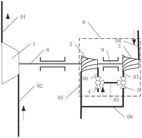
[0014] combine Figure 1~3 , The supercharger of the present invention includes: a turbine 1, a compressor 6 and a shaft A segment 8.

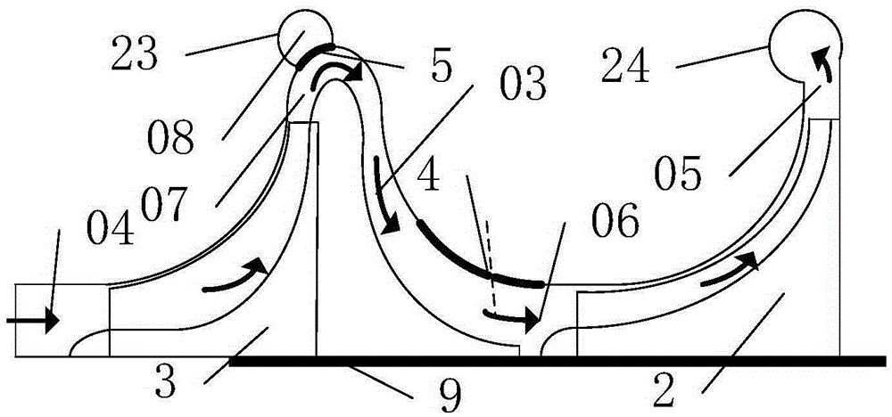
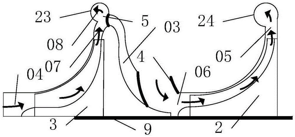
[0015] In the present invention, the structure of the compressor is improved on the basis of the original compressor. The structure of the compressor 6 includes: inlet air passage I04, impeller A3, outlet air passage I07, switching control valve I5, communication air passage I03 , Connecting gas path Ⅱ08, switching control valve Ⅱ4, inlet gas path Ⅱ06, impeller B2, connecting gas path Ⅱ08 and outlet gas path Ⅱ05.

[0016] The turbocharger has two shafts: the shaft A section 8 and the shaft B section 9. Since the two shafts are on one shaft, the rotation speeds of the turbine 1, the impeller B2 and the impeller A3 are the same.

[0017] The turbine 1 is connected to the exhaust pipe of the internal combustion engine through the i...


PUM


Abstract

The invention provides a turbocharger structure capable of achieving single-stage supercharging and two-stage supercharging. The turbocharger structure capable of achieving single-stage supercharging and two-stage supercharging comprises a turbine and an air compressor. The air compressor comprises an impeller A and an impeller B. The impeller A is connected with the atmosphere through an inlet air circuit I, so that air is introduced into the air compressor. A switching control valve I is connected to the rear portion of the outlet air circuit I of the impeller A, and the air circuit is divided into two branches behind the switching control valve I, one branch of the air circuit is connected with a communication air circuit I, and the other branch of the air circuit is connected with a communication air circuit II. A switching control valve II is installed on an inlet air circuit II of the impeller B and connected with two air circuits, one air circuit is connected with the communication air circuit I, and the other air circuit is connected with the atmosphere. The outlet air circuit II of the impeller B and the communication air circuit II are connected with an air inlet pipe of an internal combustion engine after being connected and converged into one air circuit, so that compressed air is supplied to the internal combustion engine. According to the turbocharger structure capable of achieving single-stage supercharging and two-stage supercharging, switching between two-stage supercharging and single-stage supercharging can be achieved, and the structural dimension of a supercharging system can be obviously reduced.

Description

technical field [0001] The invention relates to an internal combustion engine, specifically a supercharger of a turbocharged internal combustion engine. Background technique [0002] The use of two-stage supercharging can improve the efficiency of the supercharger and improve the economy and emission of the supercharged internal combustion engine, so it has been widely used. But at this stage, this supercharging technology is generally realized by connecting several sets of superchargers through pipelines and valves. The disadvantage is that too many pipelines and valves will occupy a lot of space. In order to save space, the patent with publication number CN104612983A proposes a single-shaft serial two-stage compressor structure, but the disadvantage of this structure is that it can only perform two-stage supercharging instead of single-stage supercharging. Contents of the invention [0003] The object of the present invention is to provide a single-stage and two-stage t...

Claims


Application Information

Patent Timeline
IPC IPC(8): F02B37/12F04D17/12F04D29/28
CPCY02T10/12
Inventor 王银燕孙永瑞王贺春杨传雷祖象欢李旭
Owner HARBIN ENG UNIV
Features
  • Generate Ideas
  • Intellectual Property
  • Life Sciences
  • Materials
  • Tech Scout
  • Unparalleled Data Quality
  • Higher Quality Content
  • 60% Fewer Hallucinations
Learn More