Disc brake assembly and method of manufacture

A technology of disc brakes and components, applied in the direction of brake components, brake types, axial brakes, etc.

Active Publication Date: 2019-03-29
DANFOSS AS
View PDF5 Cites 0 Cited by
  • Summary
  • Abstract
  • Description
  • Claims
  • Application Information

AI Technical Summary

Problems solved by technology

[0005] The above-mentioned prior art brakes have in service the problem of cantilevered axial bending of the radially inward region of the pressure plate 1 under the urging of the spring 12, so that the radially inward portion of the pressure plate 1 follows the direction of FIGS. 6 and 7 Axial bending in the left direction in , causes the braking force to be localized on the radially inward region of the rotor disk; and, therefore, provides an initial detent torque that is less than the desired level through brake engagement

Method used


Image

  • Disc brake assembly and method of manufacture
  • Disc brake assembly and method of manufacture
  • Disc brake assembly and method of manufacture

Examples


Embodiment Construction

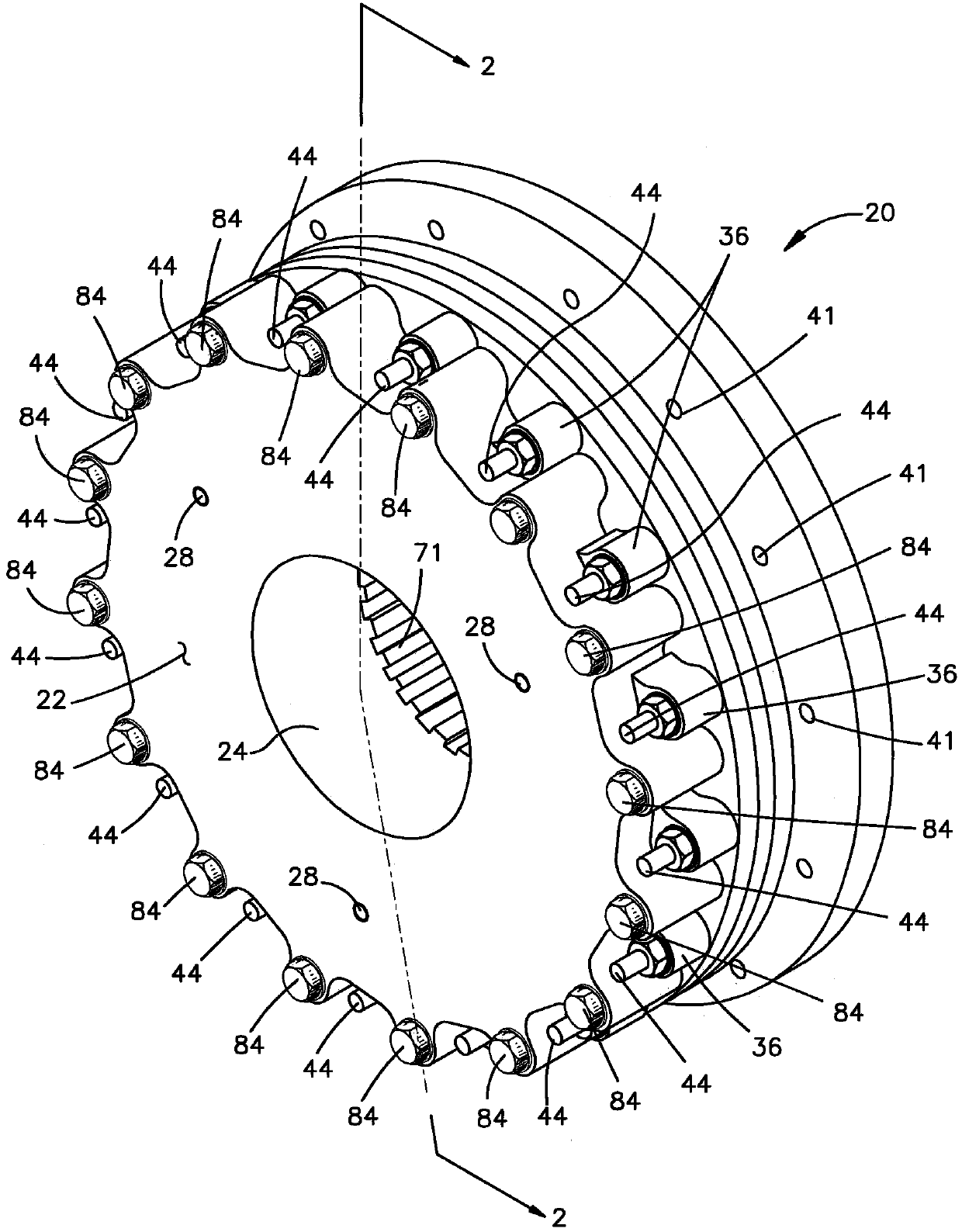
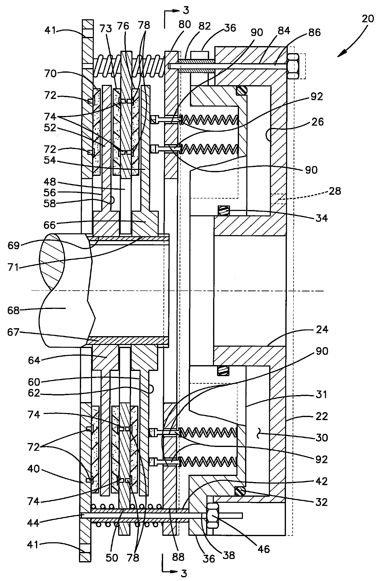
[0019] see Figure 1-5 , a disc brake assembly according to the present invention is generally indicated at 20 and includes a housing 22 of generally annular configuration with an inner circumference 24 sized to allow a rotating shaft of a desired diameter in a manner having the desired clearance through. The housing 22 includes an annular chamber 26 cooperating with an annular piston 31 disposed therein to define an annular fluid pressure chamber 30 . Chamber 30 has a plurality of fluid pressure inlets 28 formed through housing 22 . Piston 31 is sealed in annular cavity 26 around the radial periphery of cavity 26 by a suitable sealing ring 32 ; and the radial inner circumference of cavity 26 is sealed around piston 22 by an inner sealing ring 34 .

[0020] The annular piston 31 has a plurality of circumferentially spaced radially outwardly extending circumferentially spaced lugs 36 each having an aperture 38 formed axially therethrough.

[0021] An annular stationary mount...


PUM


Abstract

The invention relates to a disc brake assembly and a manufacturing method thereof. The disc brake assembly is provided with one or more rotor discs provided with annular friction surfaces and capable of performing axial movement, wherein the rotor discs are arranged between an annular piston in an annular pressure cavity in a housing and an annular reverse action plate attached and connected to the piston in the axial direction. A friction sheet is arranged on the reverse action plate and is further arranged on an annular reverse action disc located between the rotor discs and capable of performing axial movement. A positioning plate is arranged between the piston and the rotor discs, poppets capable of performing axial movement are arranged on the positioning plate, and each poppet is provided with a friction sheet for being in contact with the adjacent rotor discs. Springs on the poppets enable the poppet sheets, the rotor discs and the friction sheets to be axially biased together, and accordingly a required initial braking torque is provided. After a fluid pressure is exerted on a piston cavity, the housing enables the positioning plate to move so as to move the poppets, and accordingly the braking torque is released.

Description

technical field [0001] The present invention relates to a disc brake assembly having one or more rotating discs having an annular friction surface thereon against which is a stressed stationary friction plate / pad for applying a braking force to the rotating disc piece. In particular, the invention relates to disc brakes of the type having brake pads actuated by springs for providing the required braking force to contact an annular friction surface on the rotor disc for disengagement or activation torque on the disc. This type of disc brake utilizes an annular piston that responds to fluid pressure applied in an annular pressure chamber to move the piston axially to release the piston plate from the annular disc and thus release the braking force on the disc. Background technique [0002] Disc brakes of the type described above are used in heavy machinery applications such as oil well drilling rigs and surface production equipment; and, in certain applications, can be used ...

Claims


Application Information

Patent Timeline
Patent Type & Authority Patents(China)
IPC IPC(8): F16D55/24F16D65/14F16D65/097F16D121/04
Inventor T·汶芃玛尼E·L·鲁尔林
Owner DANFOSS AS
Why Eureka
Try Eureka