Disc brake and vehicle

A technology of disc brakes and brake pads, applied in the direction of brake types, axial brakes, brake actuators, etc., can solve the problems of low braking comfort performance, hydraulic oil leakage, slow dynamic response of braking, etc. Achieve the effects of improving braking stability, preventing rapid wear, and uniform force distribution

Active Publication Date: 2021-02-26
BYD CO LTD
View PDF8 Cites 0 Cited by
  • Summary
  • Abstract
  • Description
  • Claims
  • Application Information

AI Technical Summary

Problems solved by technology

[0002] In traditional hydraulic or pneumatic brakes, there are obvious shortcomings such as complex gas-liquid pipelines, difficult maintenance, complex layout structure, slow dynamic response of braking, and low braking comfort performance.
For example, in hydraulic brakes, the brake pedal will rebound and vibrate when the anti-lock brake is activated, which affects the braking comfort performance.
For another example, due to the use of conventional hydraulic brake components such as a larger vacuum brake booster, brake master cylinder, and oil reservoir in the traditional hydraulic brake, it not only has a complex structure and assembly, but also has a large volume and is difficult to maintain. Difficult problem, and because the system is equipped with hydraulic brake lines and brake fluid connected to the corresponding components, it is necessary to replace the hydraulic oil regularly and check whether there is a problem of hydraulic oil leakage

Method used


Image

  • Disc brake and vehicle
  • Disc brake and vehicle
  • Disc brake and vehicle

Examples


Embodiment Construction

[0054] Specific embodiments of the present disclosure will be described in detail below in conjunction with the accompanying drawings. It should be understood that the specific embodiments described here are only used to illustrate and explain the present disclosure, and are not intended to limit the present disclosure.

[0055] In the present disclosure, the orientation words such as "inside and outside" used refer to the inside and outside of the outline of the corresponding part unless stated otherwise.

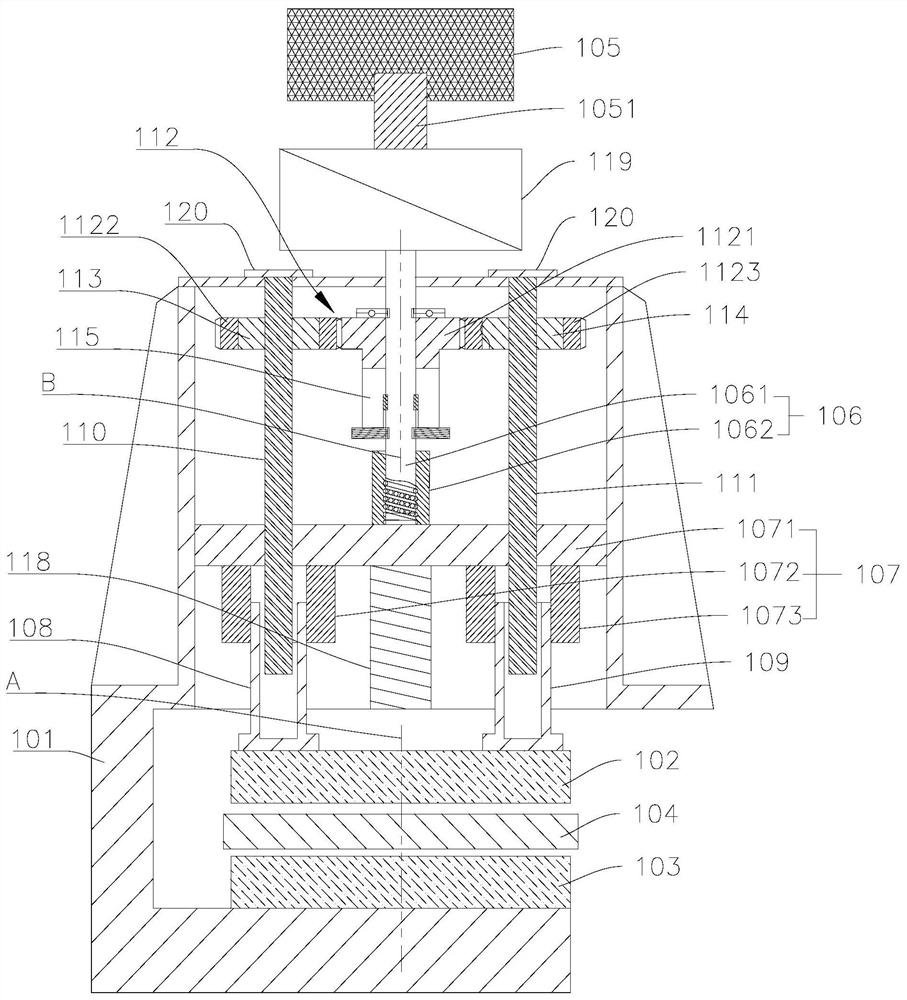
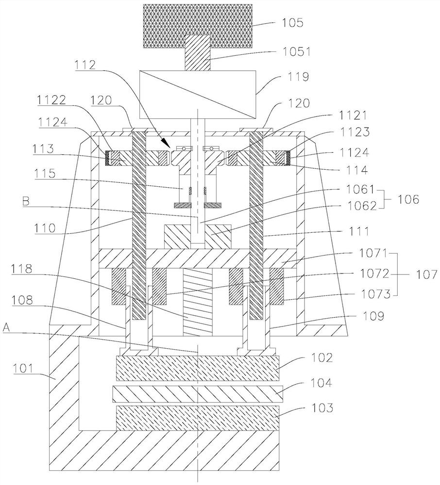
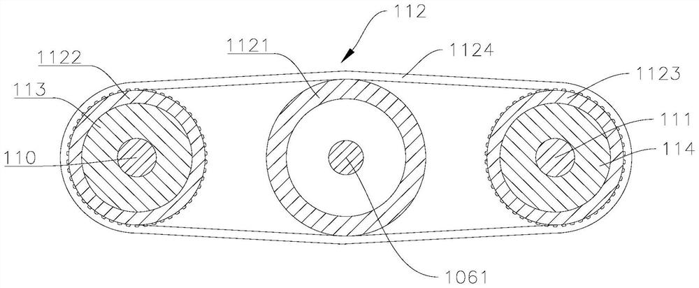
[0056] like Figure 1 to Figure 6 As shown, the present disclosure provides a disc brake, including a brake caliper body 101, a first brake block 102, a brake disc 104, a motor 105, a screw mechanism 106, a cross arm 107, a first piston 108 and a second The piston 109 and the cross arm 107 can move axially and are fixed in the brake caliper body 101. The screw mechanism 106 includes a lead screw 1061 and a nut 1062. The nut 1062 is fixed on the cross arm 107, and one end ...


PUM


Abstract

The invention relates to a disc brake and a vehicle. The brake comprises a brake caliper body, a first brake block, a brake disc, a motor, a lead screw mechanism, a cross arm, a first piston and a second piston, wherein the cross arm can axially move and is fixed in the brake caliper body; the lead screw mechanism comprises a lead screw and a nut; the nut is fixed to the cross arm; one end of thelead screw extends into the brake caliper body and is in threaded fit with the nut; the first piston and the second piston are symmetrically arranged on the side, away from the nut, of the cross arm with respect to the central axis of the first brake block; and the motor is used for driving the lead screw to rotate, so that the nut pushes the cross arm to move in the axial direction of the lead screw, and the first piston and the second piston jointly push the first brake block to move so as to press the brake disc. According to the technical scheme, the first piston and the second piston jointly push the first brake block, so that the first brake block is uniform in stress distribution and can be in uniform contact with the brake disc, the brake stability is improved, and rapid abrasion of the first brake block can be prevented.

Description

technical field [0001] The present disclosure relates to the technical field of brakes, in particular, to a disc brake and a vehicle using the disc brake. Background technique [0002] In traditional hydraulic or pneumatic brakes, there are obvious disadvantages such as complex gas-liquid pipelines, difficult maintenance, complex layout structure, slow dynamic response of braking, and low braking comfort performance. For example, in hydraulic brakes, the brake pedal will produce rebound vibration when the anti-lock brake is activated, which affects the braking comfort performance. For another example, due to the use of conventional hydraulic brake components such as a larger vacuum brake booster, brake master cylinder, and oil reservoir in the traditional hydraulic brake, it not only has a complex structure and assembly, but also has a large volume and is difficult to maintain. It is a difficult problem, and because the system is equipped with hydraulic brake lines and brak...

Claims


Application Information

Patent Timeline
Patent Type & Authority Applications(China)
IPC IPC(8): F16D55/226F16D65/14F16D65/54F16D121/20F16D121/04
CPCF16D55/226F16D65/14F16D65/54F16D2121/20F16D2121/04
Inventor 胡文中李小刚赵飞林
Owner BYD CO LTD
Why Eureka
Try Eureka