
Electromagnetic self-closing valve
A self-closing valve, electromagnetic technology, applied in the direction of valve details, valve device, functional valve type, etc., can solve the problems of large manpower, waste, and inability to ensure gas supply in time.
- Summary
- Abstract
- Description
- Claims
- Application Information
AI Technical Summary
Problems solved by technology
Method used
Image

Examples
Embodiment Construction
[0013] The present invention will be further described below in conjunction with the accompanying drawings and embodiments.
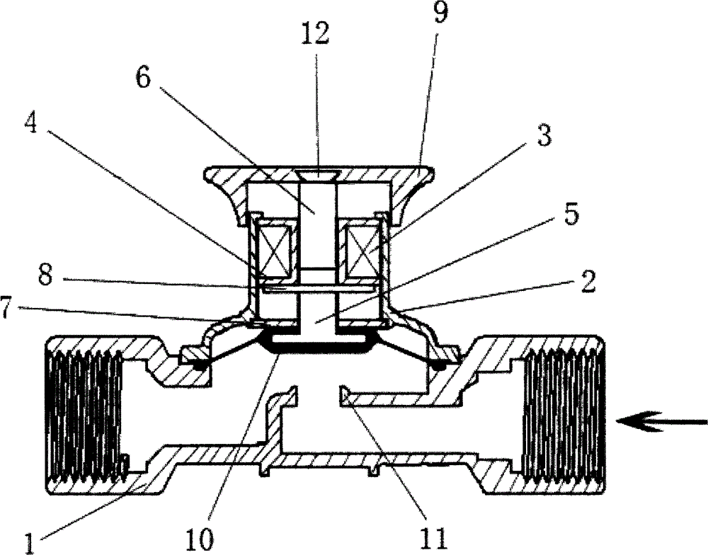
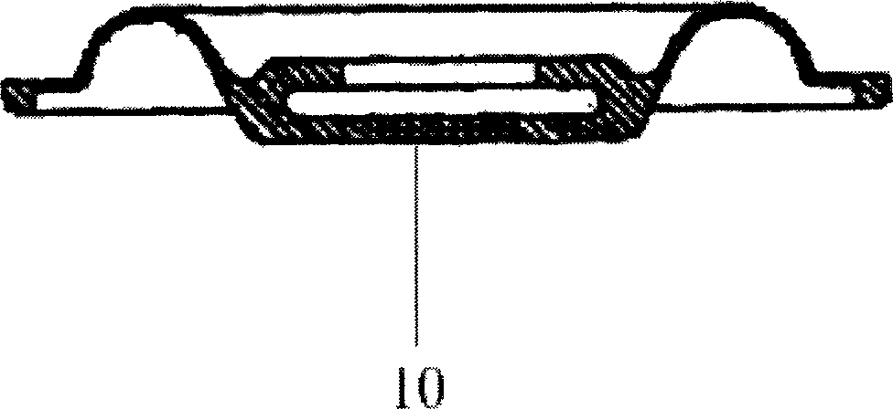
[0014] Such as figure 1 , figure 2 As shown, the waist in the bonnet 2 is provided with an annular soft magnetic sheet 7, and the top is provided with an electromagnetic coil 3 and its support 4; an iron core 6 is interspersed in the middle of the support, and the upper end of the iron core is connected in series with the handle 9 by a screw 12. The lower end of the core is closely connected to the pull rod 5 , the bottom end surface of the pull rod is fastened with the buckle diaphragm 10 , and the ring magnet 8 is fastened on the top of the pull rod 5 . The coil support 4 also plays a position-limiting role when the valve is opened. The ring magnet 8 is located between the coil support 4 and the ring soft magnetic sheet 7, and moves up and down with the pull rod 5 during the valve switch process. The pull rod 5 is made of non-magnetic material, an...
PUM
 Abstract
Description
Claims
Application Information