
Standard Calibration Rotor for Dynamic Balancing Machine with Inner Taper

A technology of dynamic balancing machine and inner cone surface, which is applied in static/dynamic balance testing, machine/structural component testing, measuring devices, etc. It can solve problems affecting the performance of the whole machine, avoid measurement errors, and reduce system The effect of measurement error

Active Publication Date: 2018-07-13
CHINA NUCLEAR TIANJIN TECH DEV
View PDF5 Cites 0 Cited by
  • Summary
  • Abstract
  • Description
  • Claims
  • Application Information

AI Technical Summary

Problems solved by technology

This kind of cylinder is made of filament winding, whether the winding is uniform or not, and the shape and position error after machining will directly affect the imbalance of the cylinder, and then affect the performance of the whole machine after assembly

Method used


Image

  • Standard Calibration Rotor for Dynamic Balancing Machine with Inner Taper
  • Standard Calibration Rotor for Dynamic Balancing Machine with Inner Taper
  • Standard Calibration Rotor for Dynamic Balancing Machine with Inner Taper

Examples


Embodiment Construction

[0023] Below, the present invention is described in detail with reference to accompanying drawing and embodiment:

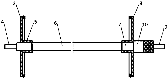
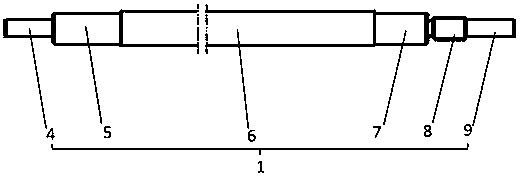
[0024] Such as Figure 1~6 As shown, a standard calibration rotor of a dynamic balancing machine with an inner cone, including a mandrel 1, the mandrel 1 from left to right includes a left support section 4 supported on the bearing frame of the balancing machine, and a center hole of the left end cover 2 The interference fit section 5 of the interference fit, the limit section 6 of the axial limit, the clearance fit section 7 of the clearance fit with the center hole of the right end cover 3, the thread section 8 of the lock nut 10, and the right support section 9, An assembly ring 11 is formed on the opposite end surfaces of the left end cap 2 and the right end cap 3 , the inner ring of the assembly ring 11 is a conical surface, and a plurality of threaded holes 12 matching the test weight are formed in the radial direction of the assembly ring 11 .

[0025] Th...


PUM


Abstract

The invention discloses a dynamic balancing machine standard correction rotor with an internal conical surface. The dynamic balancing machine standard correction rotor comprises a central spindle, wherein the central spindle comprises a left supporting section supported on a balancing machine bearing bracket, an interference fit section in interference fit with a central hole in a left end cover, a limiting section for performing axial limiting, a clearance fit section in clearance fit with a central hole in a right end cover, a threaded section matched with a locking nut and a right supporting section from the left to the right, wherein assembling rings are formed on the opposite end surfaces of the left end cover and the right end cover; the inner ring of each assembling ring is a conical surface; and multiple threaded holes matched with a test mass are formed in the radial direction of the assembling rings. According to the left end cover and right end cover with internal conical surfaces as well as the threaded holes in the assembling rings, real-time correction of a dynamic balancing machine is realized, and due to a chamber structure of the internal conical surface, a composite material cylinder can be subjected to line contact positioning, so that a measuring error introduced by the processing quality of the cylindrical end surface can be effectively avoided, and the system measuring error brought by the initial unbalance quantity of a positioning tool is reduced to the greatest degree.

Description

technical field [0001] The invention belongs to a calibration device, in particular to a standard calibration rotor of a dynamic balancing machine with an inner cone. Background technique [0002] The composite cylinder is a part of high-speed rotating machinery, and its initial imbalance will directly affect its radial vibration amplitude. This kind of cylinder is made of filament winding, whether the winding is uniform or not, and the shape and position error after machining will directly affect the imbalance of the cylinder, and then affect the performance of the whole machine after assembly. In order to accurately measure the initial unbalanced mass of the cylinder, it is necessary to design a special auxiliary positioning device for dynamic balancing. In order to meet the real-time calibration of the dynamic balancing machine, it is necessary to design a device that can simultaneously satisfy the cylinder dynamic balance detection and positioning and balancing machine c...

Claims


Application Information

Patent Timeline
Patent Type & Authority Patents(China)
IPC IPC(8): G01M1/38
Inventor 王斌李超
Owner CHINA NUCLEAR TIANJIN TECH DEV
Learn More