Parallel power conversion control device for parallel power conversion system

A technology of power conversion and control devices, applied in the direction of electrical program control, comprehensive factory control, comprehensive factory control, etc., can solve the problems affecting the tracking effect of the inverter, and achieve the effect of overcoming the poor effect of circulating current suppression

Active Publication Date: 2016-02-10
SHANGHAI MITSUBISHI ELEVATOR CO LTD
View PDF6 Cites 11 Cited by
  • Summary
  • Abstract
  • Description
  • Claims
  • Application Information

AI Technical Summary

Problems solved by technology

However, the independent current tracking method is to set the current command value of each inverter as n (n ≥ 2, the number of inverters) equal division of the total expected current, and make the actual current of each inverter track its actual current through control. The current command value can be used to achieve the two control objectives of the parallel power conversion system at the same time - the tracking of the total output current of all inverters to the total expected current and the suppression of circulating current. If the circulating current controller is simply added, the circulating current controller will The compensation of the output to the modulated voltage signal has an adverse effect on the tracking of the current command value of the inverter by the output current of a single inverter, and finally affects the tracking effect of the total output current of all inverters on the total current command value

Method used


Image

  • Parallel power conversion control device for parallel power conversion system
  • Parallel power conversion control device for parallel power conversion system

Examples


Embodiment 1

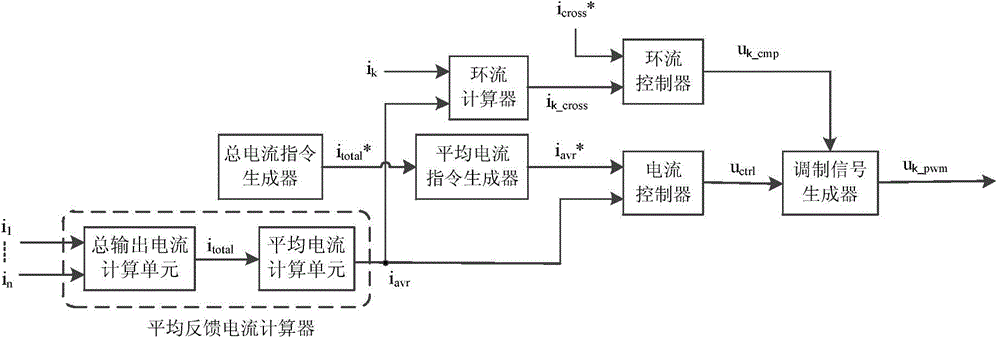
[0028] The structure of the parallel power conversion control device used in the parallel power conversion system composed of at least two power converters connected in parallel in the present invention is as follows: figure 1As shown, it is mainly composed of a total current command generator, an average current command generator, a current controller, a circulating current calculator, a circulating current controller, a modulation signal generator, and an average feedback current calculator. The total current command generator is used to generate the total current command value that the parallel power conversion system should output; the average current command generator is used to generate the average current of the power converter according to the total current command value generated by the total current command generator command value; the circulating current calculator is used to calculate the circulating current of the corresponding power converter according to the outp...

Embodiment 2

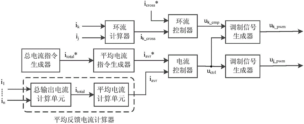
[0036] Such as figure 2 As shown, this embodiment is similar to Embodiment 1, and only the differences from Embodiment 1 will be described below.

[0037] In this embodiment, the parallel power conversion control device first selects the jth power converter as the reference power converter. For the control of any other non-reference power converter (such as the power converter numbered k, k≠j), the corresponding circulating current calculator is based on the current detection value of the kth power converter and the reference power The current detection value of the converter is used to calculate the circulating current of the kth power converter, that is, the current detection value of the reference power converter is subtracted from the current detection value of the kth power converter, and the resulting difference is used as the kth power converter circulation. The modulation signal generator corresponding to the reference power converter is only based on the control vo...


PUM


Abstract

The present invention discloses a parallel power conversion control device for a parallel power conversion system. The parallel power conversion control device for the parallel power conversion system comprises a total current instruction generator, an average current instruction generator, an average feedback current calculator, a current controller, a circulation calculator, a circulation controller configured to control the circulation of power convertors and output circulation offset voltage signals according to the results calculated by the circulation calculator, and a modulating signal generator configured to generate modulation signals required by pulse width modulation of a PWM unit according to the control voltage signals output by the current controller and the circulation offset voltage signals output by the circulation controller. The parallel power conversion control device for a parallel power conversion system is able to effectively improve the tracking performance and the circulation inhibition effect of total output current to a total current instruction value, and effectively reduce the calculated load of a microprocessor.

Description

technical field [0001] The invention relates to the control field of power conversion devices, in particular to a parallel power conversion control device for a parallel power conversion system composed of at least two power converters connected in parallel. Background technique [0002] The parallel connection of power conversion devices is an important technical means to expand the power of power conversion devices, improve reliability, and realize flexible power adjustment of power conversion devices. Document 1 (multi-inverter parallel control technology for motor drive system, Journal of Electric Machine and Control, 2010, 14(2): 36-40, 46) proposes to independently control each inverter to make its current track its expected value , so as to realize the tracking of the total current of each inverter to its command value (subsequently referred to as the independent current tracking method). Although it sets the current command value of each inverter as an equal divisio...

Claims


Application Information

Patent Timeline
Patent Type & Authority Applications(China)
IPC IPC(8): G05B19/418
CPCY02P90/02
Inventor 陈玉东
Owner SHANGHAI MITSUBISHI ELEVATOR CO LTD
Why Eureka
Try Eureka