

Composite magnetic powder and chip coil component using same
A technology of composite magnetic powder and coil components, which is applied in the direction of loop antennas with ferromagnetic material cores, magnetic materials, magnetic objects, etc., can solve problems such as parasitic capacitance degradation, reduce magnetic permeability loss, increase magnetic The effect of conductivity
Inactive Publication Date: 2016-02-10
SAMSUNG ELECTRO MECHANICS CO LTD
View PDF7 Cites 4 Cited by
- Summary
- Abstract
- Description
- Claims
- Application Information
AI Technical Summary
Problems solved by technology
[0007] Recently, depending on the high frequency of passive products, when using a frequency bandwidth higher than several tens of GHz, there is a problem that the performance of the product is deteriorated due to the parasitic capacitance caused by the dielectric constant of the ceramic powder constituting the sheet
Method used
View moreImage
Smart ImageViewing Examples

Examples
Embodiment 1
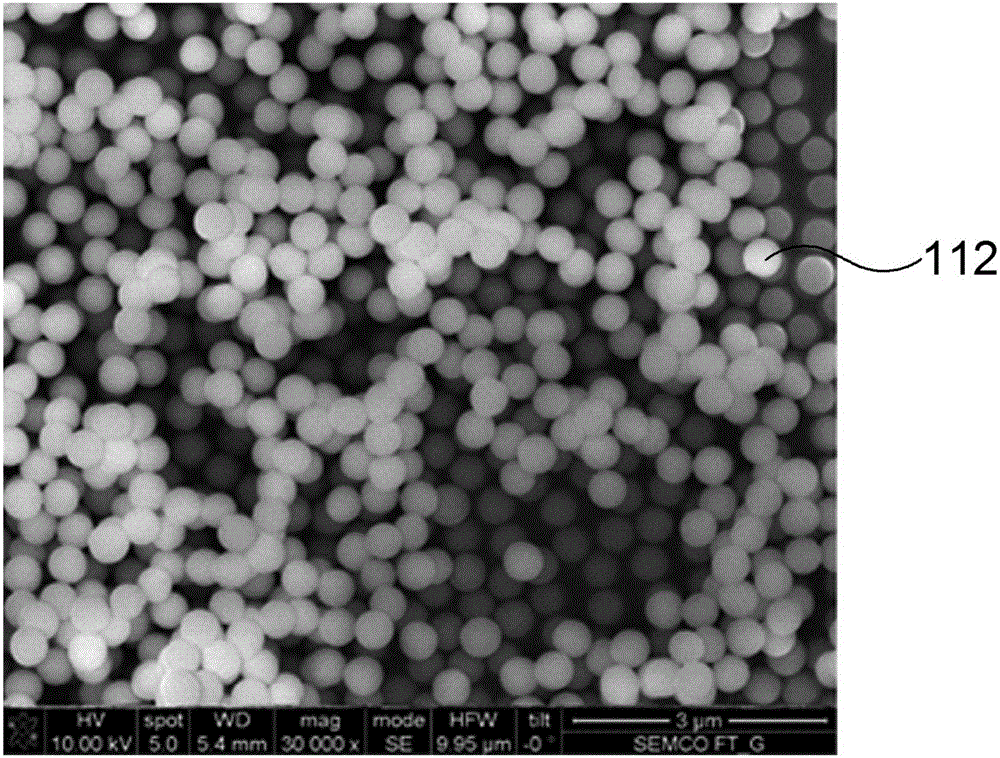
[0102] To manufacture a sample for measurement, 3 g of composite magnetic powder (SiO 2 -BaFe 12 o 19 ) was mixed with 0.3 g of epoxy adhesive, dried in an oven maintained at a temperature of 150° C., and manufactured in a standard ring shape suitable for network analyzer measurement.
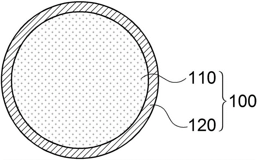
[0103] At this time, the composite magnetic powder (SiO 2 -BaFe 12 o 19 ); the ferrite powder (BaFe 12 o 19 ) coated on SiO with a thickness of 50nm 2 on the surface of the powder.
Embodiment 2
[0105] It is the same as Example 1 except that the average particle diameter is 400 nm.
Embodiment 3
[0107] Except that the thickness of the ferrite coating is 10nm, the rest is the same as the embodiment 1.
Login to View More PUM
| Property | Measurement | Unit |
|---|---|---|
| The average particle size | aaaaa | aaaaa |
| Density | aaaaa | aaaaa |
| Thickness | aaaaa | aaaaa |
Abstract
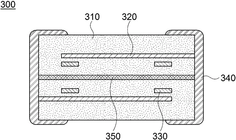
The invention relates to composite magnetic powder and a chip coil component using the same. According to the invention, the chip coil component comprises coil patterns stacked on a ceramic layer or wound on a ceramic core, wherein the ceramic layer or the ceramic core includes powder with a core-shell structure, the powder with the core-shell structure is made of SiO2 powder, and the shell is made of ferrite powder.
Description
[0001] The domestic priority application and foreign priority application claimed and incorporated by reference are as follows: This application claims the benefit of Korean Patent Application No. 10-2014-0097141 filed on July 30, 2014, which is adopted in its entirety References are included in this application. technical field [0002] The invention relates to a composite magnetic powder and a chip coil assembly using the same. Background technique [0003] Inductors in chip coil inductors have been used to remove noise or form components of LC resonance circuits (as one of the main passive devices) to form electronic circuits together with resistors and capacitors. [0004] Inductors can be manufactured by winding or printing a coil on a ferrite core and forming electrodes at both ends of the ferrite core, or by stacking after printing internal electrodes on a magnetic or dielectric material device. [0005] Inductors can be classified into multilayer, wound type, film ...
Claims
Login to View More Application Information
Patent Timeline
 IPC IPC(8): H01F27/255H01F1/11
CPCH01F1/0315H01F1/11H01F27/28H01Q7/06
Inventor金学宽李汉朴睿浚徐正旭
OwnerSAMSUNG ELECTRO MECHANICS CO LTD