Supercharge Your Innovation With Domain-Expert AI Agents!

Process for high temperature removal of trace chloride contaminants in a catalytic dehydrogenation process

A technology for catalytic dehydrogenation and chloride, applied in the direction of chemical instruments and methods, hydrocarbons, hydrocarbons, etc., can solve problems such as not very effective, high production cost, unsatisfactory large pressure drop, etc.

Active Publication Date: 2016-02-10
UOP LLC
View PDF10 Cites 1 Cited by
  • Summary
  • Abstract
  • Description
  • Claims
  • Application Information

AI Technical Summary

Problems solved by technology

However, this strategy is not very efficient and may result in increased production costs
Additionally, reducing the sorbent particle size creates an undesirably large pressure drop across the chloride remover 130

Method used


Image

  • Process for high temperature removal of trace chloride contaminants in a catalytic dehydrogenation process
  • Process for high temperature removal of trace chloride contaminants in a catalytic dehydrogenation process
  • Process for high temperature removal of trace chloride contaminants in a catalytic dehydrogenation process

Examples


Embodiment Construction

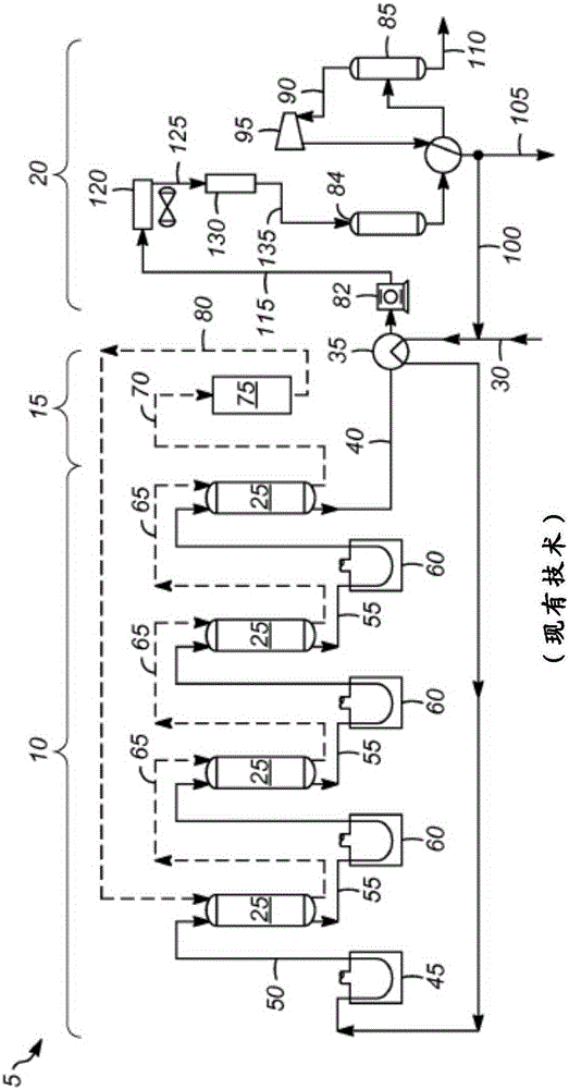
[0020] At higher temperatures, undesirable side reactions on chloride adsorbents, such as acid-catalyzed polymerization, oligomerization, cyclization and the tendency to form heavy residues by condensation, generally increase. In addition, higher temperatures are believed to unduly reduce the adsorbent capacity of the adsorption process. It is believed that optimum performance of the chloride remover can be achieved with a cooled product stream from a cooler downstream of the reactor effluent compressor in the catalytic dehydrogenation unit. Therefore, conventionally, the chloride remover is located downstream of the compressor and downstream of the cooler to impart increased adsorbent capacity, such as figure 1 shown.

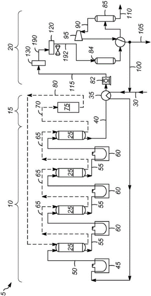
[0021] However, if there is an efficient adsorbent with suitable properties, such as low reactivity to olefin polymerization and high capacity at high operating temperatures, it is preferred that the chloride remover be located on the hotter stream prior to t...


PUM


Abstract

A process for removal of trace chloride contaminants from a reactor effluent in a catalytic dehydrogenation process is described. The reactor effluent is compressed in a compressor to provide a compressed effluent. The compressed effluent is introduced from the compressor into a chloride treater. In the chloride treater, trace chloride contaminants in the compressed effluent are adsorbed to provide a treated effluent. The treated effluent is cooled in a cooler.

Description

[0001] priority statement [0002] This application claims priority to US Application No. 13 / 922,071, filed June 19, 2013, which is hereby incorporated by reference in its entirety. Background of the invention [0003] Catalytic dehydrogenation can be used to convert paraffins to the corresponding olefins, for example propane to propylene, or butane to butenes. [0004] figure 1 A typical configuration of catalytic dehydrogenation process 5 is shown. Process 5 includes a reactor section 10 , a catalyst regeneration section 15 and a product recovery section 20 . [0005] Reactor section 10 includes one or more reactors 25 (in figure 1 4 are shown in ). Hydrocarbon feed 30 is passed to heat exchanger 35 where it is contacted with reactor effluent 40 to increase the feed temperature. Feed 30 is passed to preheater 45 where it is heated to the desired inlet temperature. Preheated feed 50 is fed from preheater 45 into first reactor 25 . Since the dehydrogenation reaction is ...

Claims


Application Information

Patent Timeline
Patent Type & Authority Applications(China)
IPC IPC(8): C07C7/12C07C7/13C07C7/20
CPCC07C5/327C07C7/12C07C11/06C07C11/08
Inventor C·P·卢布克J·K·格拉瓦拉V·I·卡纳兹雷夫
Owner UOP LLC
Features
  • R&D
  • Intellectual Property
  • Life Sciences
  • Materials
  • Tech Scout
  • Unparalleled Data Quality
  • Higher Quality Content
  • 60% Fewer Hallucinations
Learn More