Cryogenic stamping, shearing and forming device with terrace die for micro workpieces and forming method using cryogenic stamping, shearing and forming device

A micro-miniature punch technology, applied in the field of mechanical engineering, can solve the problems of low forming section accuracy, poor section topography, uneven surface, etc., achieve novel structure, reduce burrs and burrs, and improve section forming accuracy. Effect

Inactive Publication Date: 2016-02-17
JILIN UNIV
View PDF8 Cites 5 Cited by
  • Summary
  • Abstract
  • Description
  • Claims
  • Application Information

AI Technical Summary

Problems solved by technology

At present, ordinary processing methods at room temperature are still used in the punching and shearing of micro-sized workpieces, such as high-speed punching or multiple times of punching and shearing assisted by ultrasound. For small parts, ordinary punching and shearing is used. There are many burrs on the section of the workpiece, the surface is uneven, and the appearance of the section is poor, especially the precision of the formed section is low

Method used


Image

  • Cryogenic stamping, shearing and forming device with terrace die for micro workpieces and forming method using cryogenic stamping, shearing and forming device
  • Cryogenic stamping, shearing and forming device with terrace die for micro workpieces and forming method using cryogenic stamping, shearing and forming device
  • Cryogenic stamping, shearing and forming device with terrace die for micro workpieces and forming method using cryogenic stamping, shearing and forming device

Examples


Embodiment Construction

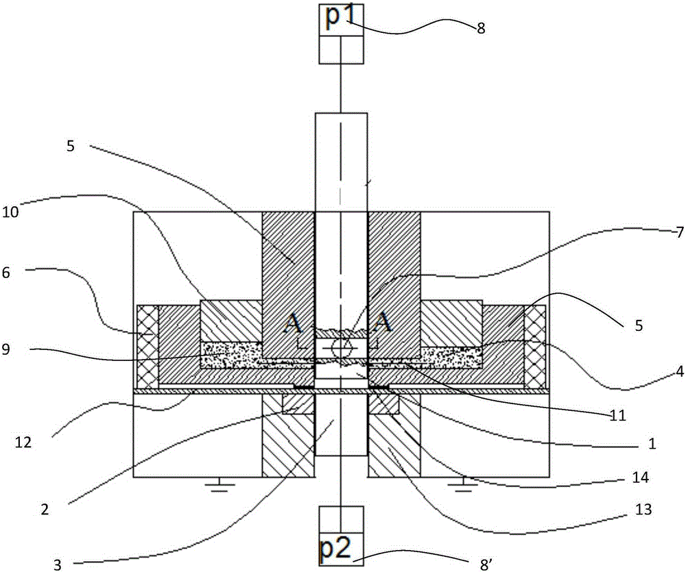
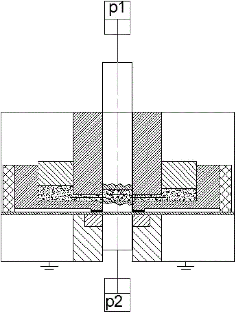
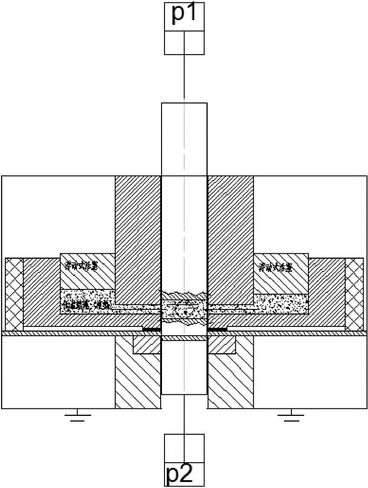
[0035] The punch 1 has a through hole 7 on its side wall, the punch 1 driven by the hydraulic cylinder P18 moves in the blank holder 5, the die 2 is placed in the die support 13 and fixed, and is driven by the hydraulic cylinder P28' The driven ejector rod 3 moves in the die 2, and a storage tank 9 that can accommodate the low-temperature solution 4 is opened in the blank holder, and a floating piston 10 is installed on the top of the storage tank 9. The side wall hole 11 for the low-temperature solution 4 to flow, the blank holder 5 can press the plate 12 against the edge of the die 2 under the action of force, and the surrounding of the blank holder 5 is covered with heat insulating material -6, heat insulating material -14 is pressed on the boundary between the blank holder 5 and the sheet material 12 .

[0036] The side wall through hole 7 of the punch 1 communicates with the side wall hole 11 of the blank holder 5 during operation.

[0037] The low-temperature solution 4...


PUM

PropertyMeasurementUnit
thicknessaaaaaaaaaa
elongationaaaaaaaaaa

Abstract

The invention relates to a cryogenic stamping, shearing and forming device with a terrace die for micro workpieces and a forming method using the cryogenic stamping, shearing and forming device, and belongs to the field of mechanical engineering. The cryogenic stamping, shearing and forming device comprises the terrace die, a hollowing block, an ejector rod, a low-temperature solution, a blank holder, a heat insulating material and a terrace die supporting base, wherein the side wall of the terrace die is locally provided with a through hole; a hydraulic cylinder drives the terrace die to move in the blank holder; the hollowing block is fixed in a hollowing block supporting base; the hydraulic cylinder drives the ejector rod to move in the hollowing block; a storage slot capable of accommodating the low-temperature solution is formed in the blank holder; the top of the storage slot is provided with a floating type piston; and the inner side wall of the blank holder is provided with a side wall hole capable of allowing the low-temperature solution to flow. The forming method based on the device comprises the five steps of clamping plates, cooling, stamping and shearing, drawing the plates out of the die and carrying out shape inspection. According to the cryogenic stamping, shearing and forming device with the terrace die for micro workpieces and the forming method using the cryogenic stamping, shearing and forming device, the advantages are that precision processing for micro workpieces is realized, deckle edges and burrs are reduced in a facilitated mode, section is flattened, section forming precision and forming precision for forming the workpieces are improved, and batched production is realized.

Description

technical field [0001] The invention belongs to the field of mechanical engineering and is used for plastic forming of punching and shearing micro-sized workpieces or through holes, in particular to a cryogenic punching and shearing forming device and a forming method of a micro-sized workpiece punch. Background technique [0002] Micro-small workpieces play a very important role in the electronics industry, and the contour and through-hole punching of micro-small workpieces play an important role in the field of micro-small workpiece processing. At present, ordinary processing methods at room temperature are still used in the punching and shearing of micro-sized workpieces, such as high-speed punching or multiple times of punching and shearing assisted by ultrasound. For small parts, ordinary punching and shearing is used. There are many burrs on the section of the workpiece, the surface is uneven, and the appearance of the section is poor, especially the precision of the f...

Claims


Application Information

Patent Timeline
Patent Type & Authority Applications(China)
IPC IPC(8): B21D28/02B21D37/16
CPCB21D28/02B21D37/16
Inventor 胡志清徐亚男刘昆赵继颜庭旭李洪杰廖伟李寿涛吕振华
Owner JILIN UNIV
Why Eureka
Try Eureka