hydraulic mount

A technology of hydraulic mounting and liquid chamber, applied in the field of auto parts, can solve the problems of high cost, can not meet the requirements of shock absorption, complex structure, etc., and achieve the effects of stable performance, reasonable design of vibration isolation mechanism, and simple overall structure.

Active Publication Date: 2018-04-03
ZHEJIANG SHITAI IND CO LTD
View PDF7 Cites 3 Cited by
  • Summary
  • Abstract
  • Description
  • Claims
  • Application Information

AI Technical Summary

Problems solved by technology

However, the existing hydraulic mounts still have the following disadvantages: the existing hydraulic mounts usually only have a good shock absorption effect in a certain frequency range, and cannot meet the shock absorption requirements in the entire working range of the car
The newly proposed active mount technology makes up for the lack of high-frequency performance of traditional hydraulic mounts through active actuators for shock absorption in the high-frequency range, but its structure is complex and the cost is high

Method used


Image

  • hydraulic mount
  • hydraulic mount

Examples


Embodiment 1

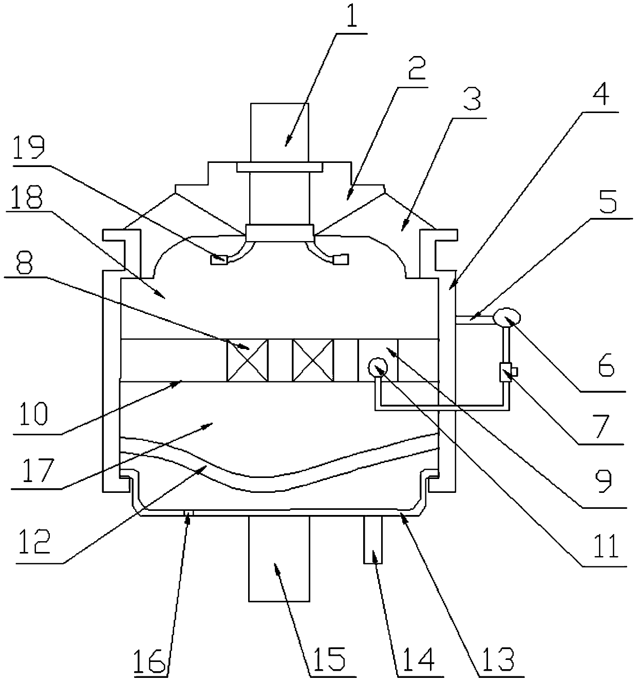
[0019] New hydraulic mounts, such as figure 1 As shown, it includes a rubber main spring 3, a housing 4 and a bottom film 12. The rubber main spring 3, the housing 4 and the bottom film 12 form a cavity filled with magnetorheological fluid, and a vibration isolation mechanism 10 is arranged in the cavity. The vibration mechanism 10 divides the cavity into an upper liquid chamber 18 and a lower liquid chamber 17. The vibration isolation mechanism 10 is provided with a ring coil 8, and the two ends of the ring coil 8 are connected to a power supply. The vibration isolation mechanism 10 is provided with an inertia channel 9. Magneto-rheological fluid is a suspension composed of tiny soft magnetic particles with high magnetic permeability and low hysteresis and a non-magnetic liquid. This suspension exhibits low-viscosity Newtonian fluid characteristics under zero magnetic field conditions; Under the action of a strong magnetic field, it exhibits high viscosity and low flow charac...

Embodiment 2

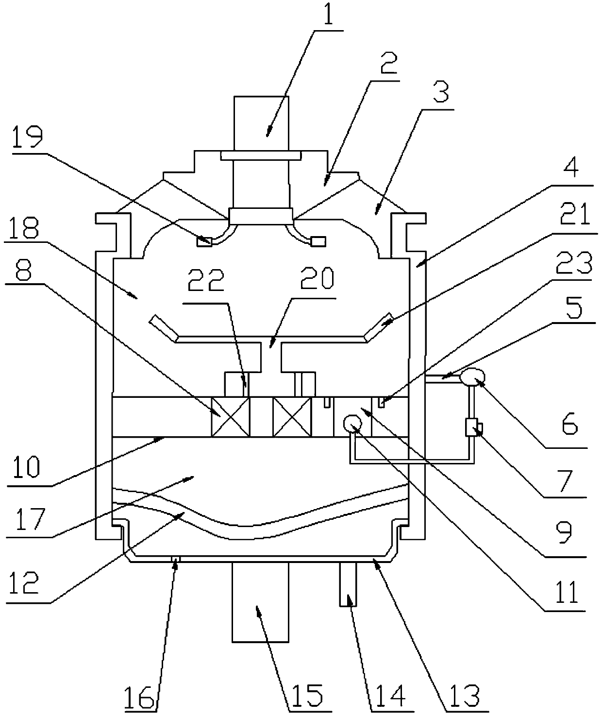
[0027] With embodiment 1, the difference is as figure 2 As shown, the isolation plate 20 is provided on the vibration isolation mechanism 10, and the two ends of the isolation plate 20 are provided with sloping plates 21. The sloping plates 21 are arranged obliquely upward. When the upper connecting bolt 1 is squeezed, the liquid below the upper connecting bolt 1 The deformation is the largest, and the liquid flows to the inertial channel 9 along the isolation plate 20, the isolation plate 20 changes the flow direction of the liquid, increases the liquid flow distance, and consumes energy when the liquid flows, thereby increasing the damping of the hydraulic mount; the inclined plate 21 and the isolation plate 21 The space of the vibration mechanism 10 is larger than the space between the isolation plate 20 and the vibration isolation mechanism 10. Since the liquid flows from the large space to the small space, the liquid is squeezed and the damping becomes larger, thereby inc...


PUM


Abstract

The invention relates to auto parts and discloses a novel hydraulic mount, which includes a rubber main spring (3), a casing (4) and a bottom film (12), a rubber main spring (3), a casing (4) and a bottom film (12 ) to form a cavity filled with magnetorheological fluid, and a vibration isolation mechanism (10) is arranged in the cavity, and the vibration isolation mechanism (10) divides the cavity into an upper liquid chamber (18) and a lower liquid chamber (17). The vibration mechanism (10) is provided with an annular coil (8), and the two ends of the annular coil (8) are connected to the power supply; the vibration isolation mechanism (10) is provided with an inertial channel (9), and an inflatable ring is arranged in the inertial channel (9). (11), the inflatable ring (11) is connected with a solenoid valve (7), and the solenoid valve (7) is connected with an air pump (6). The invention uses magnetism to adjust the damping of the hydraulic mount, and has the characteristics of simple and compact structure and easy installation.

Description

technical field [0001] The invention relates to auto parts, in particular to a novel hydraulic mount. Background technique [0002] Automotive engine hydraulic mount refers to the elastic connection system between the engine powertrain and the vehicle frame. The design of the system’s vibration damping performance is directly related to the transmission of engine vibration to the vehicle body, which affects the NVH performance of the vehicle. Specifically, the hydraulic mount is an important part of the car. It is mainly used to reduce the vibration transmitted from the engine to the body, while controlling the displacement of the engine, resisting the torque of the engine, and reducing the vibration transmitted from the tire to the powertrain on potholes. shock. Therefore, it is required that the hydraulic mount not only has good vibration isolation ability, but also has a good ability to block shock. Existing hydraulic mounts mainly include simple orifice type, inertial ...

Claims


Application Information

Patent Timeline
Patent Type & Authority Patents(China)
IPC IPC(8): B60K5/12F16F15/027
Inventor 陈建会陈中敢
Owner ZHEJIANG SHITAI IND CO LTD
Why Eureka
Try Eureka