Automatic drawing brick clamping machine

A brick clamping machine and automatic technology, applied in the field of machinery, can solve the problems of reducing the effect of manual loading and unloading of bricks, the number of bricks clamped by the manipulator is small, and the range of loading and unloading areas is narrow, so as to achieve flexible loading and unloading, improve handling efficiency, and have a wide range of applications Effect

Inactive Publication Date: 2016-02-17
张利平 +1
View PDF7 Cites 6 Cited by
  • Summary
  • Abstract
  • Description
  • Claims
  • Application Information

AI Technical Summary

Problems solved by technology

However, the number of bricks clamped by the manipulator is small, only 4-8 bricks, the loading and unloading area is na

Method used


Image

  • Automatic drawing brick clamping machine
  • Automatic drawing brick clamping machine

Examples


Embodiment Construction

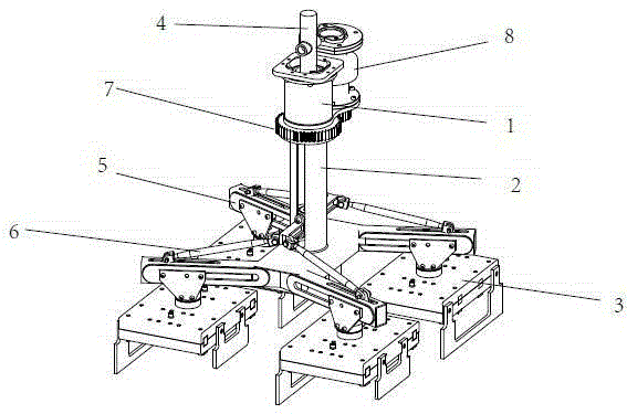
[0014] see figure 1 and figure 2 , the brick clamping machine includes a fixed rotating frame 1, a retracting guide rail 2, a movable combined brick clamp 3, a hydraulic cylinder 4, a retracting frame 5, a pull rod 6, a rotating gear 7, a reducer and a driving gear 8, and the fixed rotating frame 1 is set On the guide rail 2, a rotating gear 7 is installed on the fixed rotating frame 1, and the gear 7 meshes with the drive gear installed on the reducer shaft. The folding frame 5 is installed in the sliding groove of the folding guide rail 2. The folding frame 5 is composed of a movable combined brick clip 3 and a pull rod 6. The folding frame 5 is connected with the piston rod of the hydraulic cylinder 4, and moves along the sliding groove along with the reciprocating movement of the piston rod. Do up and down to gather and open the movement.

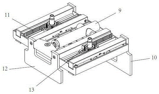
[0015] The movable combined brick clamp 3 comprises a large brick clamp 10, a small brick clamp 12, a rack 11, a brick clamp oil cy...


PUM


Abstract

The invention relates to the technical field of machines, in particular to an automatic drawing brick clamping machine. The brick clamping machine comprises a fixing rotation frame 1, a drawing guide rail 2, movable combined brick clamps 3, a hydraulic cylinder 4, drawing frames 5, pull rods 6, a rotating gear 7 and a speed reducer and drive gear 8. The drawing guide rail 2 is sleeved with the fixing rotation frame 1. The fixing rotation frame 1 is provided with the rotating gear 7. The gear 7 is meshed with a drive gear installed on a speed reducer shaft. The drawing frames 5 are installed in sliding grooves of the drawing guide rail 2. The drawing frames 5 are composed of the movable combined brick clamps 3 and the pull rods 6, are connected with a piston rod of the hydraulic cylinder 4 and do vertical drawing and expanding movement along the sliding grooves along with the reciprocating movement of the piston rod. The number of clamped and placed bricks is large, loading and unloading are flexible, the application range is wide, and the brick carrying efficiency is greatly improved.

Description

technical field [0001] The invention belongs to the technical field of machinery, and in particular relates to an automatic folding brick clamping machine required for brick making in a brick factory. Background technique [0002] In the traditional brick-making production, a large amount of labor is required to gather and transport the finished bricks, which requires a lot of labor and physical strength. In recent years, devices for clamping and transporting bricks by machinery have also emerged, such as the "Flexible Brick Clamping Manipulator" (public number CN103612907A) published by the State Intellectual Property Office on March 5, 2014. This patent includes a boom, fixed on The first cylinder of the boom, the crossbeam that is hoisted on the piston rod of the first cylinder through joint bearings, the clamp arms hinged at both ends of the beam respectively, and the second cylinder that is hinged between the two clamp arms to drive the opening and closing of the two cl...

Claims


Application Information

Patent Timeline
IPC IPC(8): B65G47/90
Inventor 张利平雷正武
Owner 张利平
Why Eureka
Try Eureka