Super pressure suction joint pumping system and operating method thereof

A technology of super pumping pipes, which is applied in infrastructure engineering, construction, etc., can solve the problems of low vacuum pumping efficiency, high labor cost, and short service life of equipment in tube wells, so as to improve water collection efficiency and pumping efficiency, facilitate installation, The effect of simple structure

Active Publication Date: 2016-02-17
SHANGHAI CHANGKAI GEOTECHN ENG
View PDF9 Cites 13 Cited by
  • Summary
  • Abstract
  • Description
  • Claims
  • Application Information

AI Technical Summary

Problems solved by technology

[0003] Traditional deep foundation pit dewatering equipment includes vacuum pumps, submersible pumps, and deep well filters. Usually, a well is equipped with a submersible pump. The submersible pump is often placed below the water surface in the well. As the depth of the well point increases, it becomes more and more difficult to pump water.
This technology requires a lot of equipment investment in the early stage. Whether it is installation, inspection or maintenance during operation, the labor cost is very high, and the pumping efficiency is not ideal, and the service life of the equipment is short.
[0004] In the patents ZL200520047130.7 (special equipment for dewatering of deep wells in foundation pits), ZL200610024254.2 (dewatering equipment for deep wells in vacuum foundation pits) and ZL201420570569.7 (dewatering devices for deep wells with negative pressure air jets in foundation pits), at the lower end of the "vacuum water distribution pipe" All are equipped with small holes. In the actual construction process, the relative position of the small hole and the groundwater level needs to be adjusted repeatedly according to the groundwater level, which consumes a lot of human resources.
[0005] However, the patent ZL200620039852.2 (intubation vacuum foundation pit deep well dewatering equipment) avoids the above problems, but the tube well vacuuming efficiency is low, the effect is poor, and the applicability to deep wells over 10m is poor
[0006] Although the above four technologies have improved the traditional downcomer wells, there is still a common deficiency: that is, there are vent holes on the manhole covers of the downcomer wells, so only a limited vacuum can be formed in the downcomer wells, which is relatively poor in permeability. Poor soil layer has very low water collection efficiency

Method used


Image

  • Super pressure suction joint pumping system and operating method thereof
  • Super pressure suction joint pumping system and operating method thereof

Examples


Embodiment 1

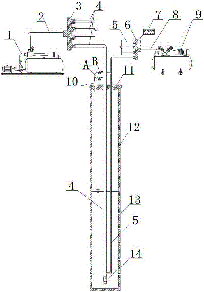
[0020] Embodiment 1: as figure 1 As shown, this embodiment specifically relates to a super pressure-suction combined pumping system and its working method. The pumping system mainly includes a downcomer well 12 , a vacuum pump 1 and an air compressor 9 .

[0021] The downfall tube well 12 is buried underground, and its upper port is slightly exposed on the ground. The downfall tube well 12 is provided with several filter holes 13 or gaps at different heights of the tube body according to the precipitation requirements of different strata, so as to serve as the channel for groundwater to enter the downfall tube well 12. The well cover 11 is sealed with the upper port of the downcomer well 12 to ensure the working efficiency of the tube well; on the well cover 11, there are also reserved communication ports for the suction pipe 4, the air pressure pipe 5 and the suction pipe 10 to run through.

[0022] The vacuum pump 1 is positioned on the ground outside the downcomer well 12, ...

Embodiment 2

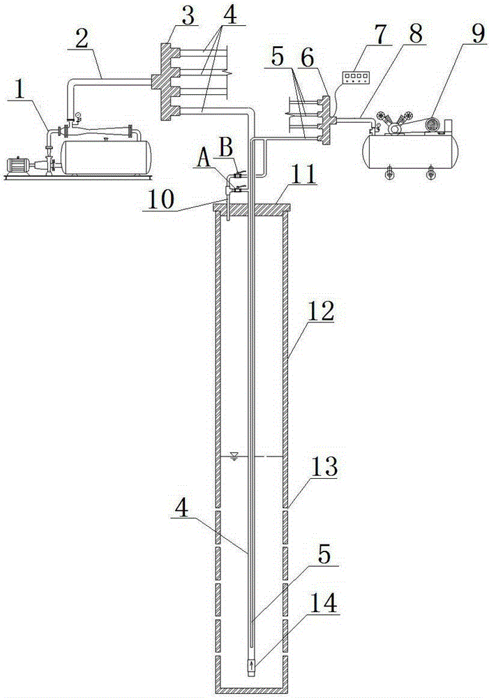
[0030] Embodiment 2: as figure 2As shown, this embodiment specifically relates to a super pressure-suction combined pumping system. The difference between this pumping system and the pumping system in Embodiment 1 is that the air pressure pipe 5 and the suction pipe 4 are arranged concentrically, specifically: Outside the downcomer well 12, the air pressure pipe 5 is connected to the water suction pipe 4 and extends into the water suction pipe 4. The two are arranged coaxially. It should be noted that the depth of the air pressure pipe 5 protruding into the water suction pipe 4 is adjustable.

[0031] When the pumping system is working, according to the observation results of the surrounding groundwater level observation wells, the extension length of the air pressure pipe 4 can be adjusted at any time to change the position of the lower port of the air pressure pipe 4, so as to avoid excessive water level difference and increase the air compressor 9 initial pressure, thus i...


PUM


Abstract

The invention discloses a super pressure suction joint pumping system and an operating method thereof. The pumping system comprises a rainfall tube well, a vacuum pump and an air compressor, wherein the vacuum pump and the air compressor are located outside the rainfall tube well; pumping pipes of the vacuum pump are connected to the inside of the bottom of the rainfall tube well; air compressor pipes of the air compressor are connected to the inside of the rainfall tube well and communicated with the pumping pipes; an exhaust tube is fixed to a well lid of the rainfall tube well; one port of the exhaust tube is formed in the upper portion of the rainfall tube well, the other end of the exhaust tube is located outside the rainfall tube well and split to two branch tubes, one branch tube is provided with a valve A and communicated with the pumping pipes, and the other branch tube is provided with a valve B and communicated with the air compressor pipes. The super pressure suction joint pumping system and the operating method thereof have the advantages that the structure is simple; all mechanical devices are disposed outside the well; installation is convenient and fast; the cost is low; one set of pumping system can drive six to twelve rainfall tube wells at the same time, and the water collecting efficiency and the pumping efficiency of the rainfall tube well can be effectively improved.

Description

technical field [0001] The invention belongs to the technical field of deep well pumping, and in particular relates to a super pressure-suction combined pumping system and a working method thereof. Background technique [0002] With the rise of urban high-rise buildings and the development of underground railways, a large number of deep foundation pit projects have been produced. If the groundwater level in the construction area is high, the excavation of the foundation pit will involve the influence of groundwater on the construction of the foundation pit. For the normal operation, it is necessary to take measures to lower the groundwater level. [0003] Traditional deep foundation pit dewatering equipment includes vacuum pumps, submersible pumps, and deep well filters. Usually, one well is equipped with one submersible pump. The submersible pump is often placed below the water surface in the well. As the depth of the well increases, it becomes more and more difficult to p...

Claims


Application Information

Patent Timeline
Patent Type & Authority Applications(China)
IPC IPC(8): E02D19/10
CPCE02D19/10
Inventor 殷立锋缪国建李宏军瞿成松陈晖徐丹张晓晖
Owner SHANGHAI CHANGKAI GEOTECHN ENG
Why Eureka
Try Eureka