Intake air recirculation fittings with ring cavity

A technology for recirculation pipes and intake pipes, which is applied to engine components, combustion air/combustion-air treatment, internal combustion piston engines, etc. It can solve the problems of affecting the working efficiency of the impeller, different guiding effects of the wind deflector, and increasing the impact of the impeller. , to achieve the effect of ensuring smooth air intake, low cost and improving working life

Active Publication Date: 2018-05-01
CHONGQING PUSH MECHANISM
View PDF7 Cites 0 Cited by
  • Summary
  • Abstract
  • Description
  • Claims
  • Application Information

AI Technical Summary

Problems solved by technology

The existing recirculation intake pipe is a welded special-shaped three-way pipe, and the intake recirculation gas is directly passed to the front of the supercharger, so that the airflow with a certain pressure will flow into the main channel and hit the supercharger. On the impeller of the compressor, the angle and pressure of the airflow entering the impeller will change, so that the guiding effect of the wind guide wheel of the impeller is different from the design value, which increases the impact of the airflow on the impeller and affects the working efficiency of the impeller. At the same time, it has a strong pressure The airflow hits the impeller, and the vibration caused by the impact will also be abnormal, and the impeller is a high-speed rotating part, and long-term accumulation will have a bad effect on the supercharger

Method used


Image

  • Intake air recirculation fittings with ring cavity

Examples


Embodiment Construction

[0013] The present invention will be further described below in conjunction with the embodiments and drawings.

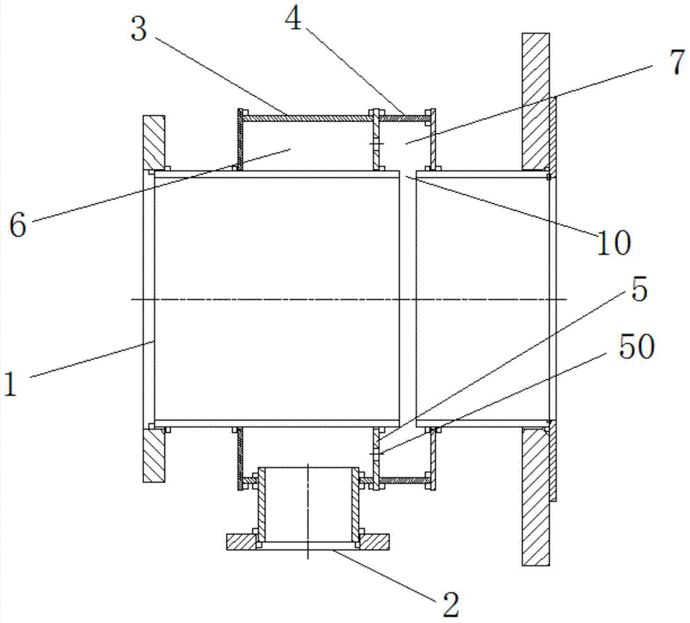
[0014] Such as figure 1 The shown intake recirculation pipe fitting with a ring cavity includes a main pipe 1. The main pipe 1 is sleeved with a first ring 3 and a second ring 4 side by side. The first ring 3 and the second ring A first ring cavity 6 and a second ring cavity 7 are formed between the ring 4 and the main pipe 1, and the first ring 3 and the second ring 4 are connected to the main pipe 1 by welding. The diameters of the first loop 3 and the second loop 4 are the same and larger than the outer diameter of the main pipe 1. The length of the first loop 3 is greater than the length of the second loop 4, so that the first loop cavity 6 The volume is greater than the volume of the second ring cavity 7, so that the circulating air can smoothly enter the second ring cavity 7 from the first ring cavity 6 to ensure the normal air intake of the main flow channel an...


PUM


Abstract

The invention discloses an air inlet recycling pipe component with annular pipeline cavities. The air inlet recycling pipe component comprises a main pipeline; a first annular pipeline and a second annular pipeline sleeve the outer side of the main pipeline; a first annular pipeline cavity and a second annular pipeline cavity are formed between the first annular pipeline and the main pipeline as well as between the second annular pipeline and the main pipeline; the first annular pipeline is connected with the second annular pipeline through an annular plate; ventilation holes are uniformly formed in the circle of periphery of the annular plate; an annular notch which is communicated with the second annular pipeline cavity is also formed in the side wall of the main pipeline; a recycling air inlet pipe is vertically arranged on the outer side of the first annular pipeline; and the recycling air inlet pipe is communicated with the first annular pipeline cavity. According to the air inlet recycling pipe component, a decompression structure formed by the parallel two-stage annular pipeline cavities is adopted, so that the structure is compact, and airflow loss is reduced while the pressure is reduced; and the phenomenon that after recycling air flows into the main pipeline, the pressure of the recycling air causes adverse influence on the working efficiency of a supercharger compressor impeller and causes turbulent flow influence on the air in the main pipeline is avoided.

Description

Technical field [0001] The invention relates to an intake recirculation pipe fitting with an annular cavity, which belongs to the field of gas recirculation systems. Background technique [0002] The loop pipe assembly is assembled between the mixed gas inlet pipe of the gas engine and the supercharger. It is the last pipe before the supercharger, that is, the mixed gas directly enters the compressor impeller of the supercharger after passing through this pipe. [0003] In the traditional gas engine, the air intake system adopts the form of intake air recirculation, that is, after the mixed gas is supercharged and intercooled, it bypasses a stream of gas to circulate the intake air before the supercharger. The existing recirculation intake pipe is a welded special-shaped three-way pipe, and the intake recirculation gas is directly passed to the front of the supercharger. In this way, the airflow with a certain pressure will flow into the main flow path and hit the supercharger. On...

Claims


Application Information

Patent Timeline
Patent Type & Authority Patents(China)
IPC IPC(8): F02B37/16F02M35/104
CPCF02B37/16F02B37/162F02M35/10091F02M35/104Y02T10/12
Inventor 黄雅婷丁超田海飞田华清
Owner CHONGQING PUSH MECHANISM
Why Eureka
Try Eureka