A pressure accumulating cavity type high pressure common rail injector side fuel injector

A high-pressure common rail, accumulating chamber technology, applied in the machine/engine, fuel injection device, engine components, etc., can solve the problems of different fuel injection amount of each cylinder, fluctuation of high-pressure rail pressure, affecting combustion characteristics, etc. Flexible way to meet the effect of stable, precise and flexible control

Active Publication Date: 2018-04-10
CHINA NORTH ENGINE INST TIANJIN
View PDF9 Cites 0 Cited by
  • Summary
  • Abstract
  • Description
  • Claims
  • Application Information

AI Technical Summary

Problems solved by technology

Therefore, the dynamic pressure stability of the high-pressure common rail system directly affects the realization of the ideal injection law of the system, which in turn affects the combustion characteristics. Because each injection of the high-pressure common-rail injector will cause pressure fluctuations in the high-pressure fuel rail, which will affect the The fuel injection quantity of the injectors of other cylinders causes the fuel injection quantity of each cylinder to be different, thus affecting the combustion characteristics

Method used


Image

  • A pressure accumulating cavity type high pressure common rail injector side fuel injector
  • A pressure accumulating cavity type high pressure common rail injector side fuel injector
  • A pressure accumulating cavity type high pressure common rail injector side fuel injector

Examples


Embodiment Construction

[0025] It should be noted that, in the case of no conflict, the embodiments of the present invention and the features in the embodiments can be combined with each other.

[0026] The present invention will be described in detail below with reference to the accompanying drawings and examples.

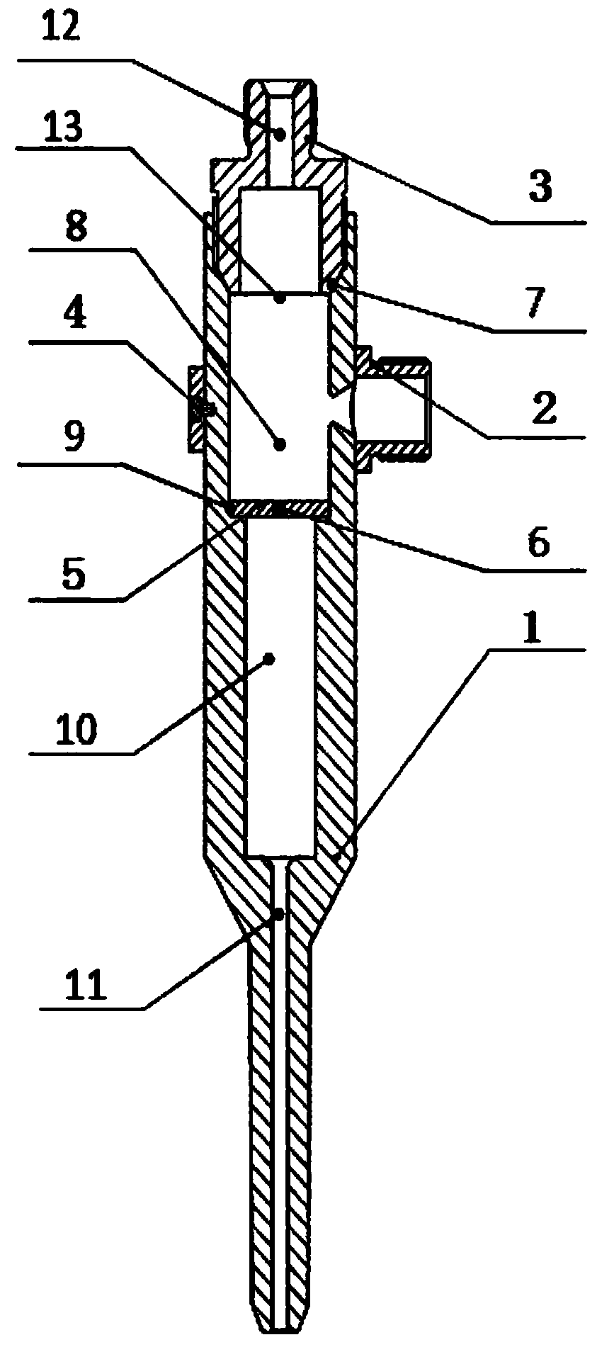
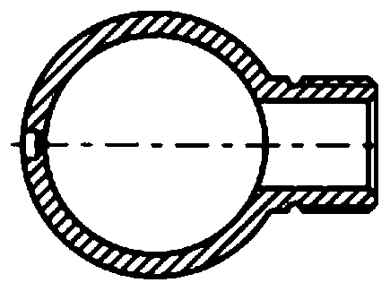
[0027] Such as Figures 1 to 6 As shown, the present invention forms a high-pressure fuel injection system together with a high-pressure fuel pump, a high-pressure common rail injector, and a series of high-pressure fuel pipes. The present invention includes a lateral oil inlet rod body 1, a sealing nut 3, an adapter 2, and a positioning screw 4 and control loop 5;

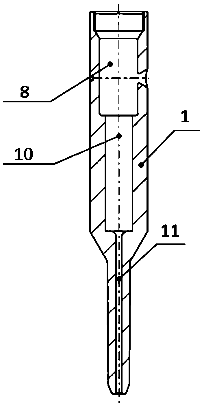
[0028] Such as figure 1 and 2 As shown, the interior of the lateral oil inlet rod body 1 is provided with a fuel supply passage 11, a pressure storage chamber 10 and an upper chamber 8 in turn from the lower end to the upper end, the fuel supply passage 11 communicates with the lower end of the pressure storage chamber 10...


PUM


Abstract

The invention provides a side oil inflow rod of a pressure storage cavity type high-pressure common rail oil sprayer. The side oil inflow rod comprises a side oil inflow rod body, a sealing nut, a transfer joint, a locating screw and a control ring. The interior of the side oil inflow rod body is sequentially provided with a fuel oil supply channel, a pressure storage cavity and an upper cavity from the lower end to the upper end, wherein the fuel oil supply channel, the pressure storage cavity and the upper cavity are sequentially communicated. The upper end of the pressure storage cavity is communicated with the lower end of the upper cavity through the control ring. The control ring is fixed to the inner side wall of the lower end of the upper cavity. A throttling hole is formed in the middle portion of the control ring. The upper end of the side oil inflow rod body is sealed through the sealing nut. The sealing nut is provided with a through hole communicated with the upper cavity. The side oil inflow rod body is sleeved with the transfer joint communicated with the upper cavity, and the transfer joint is fixed to the side wall of the side oil inflow rod body through the locating screw. By the adoption of the side oil inflow rod, the requirement for the stability of fuel oil pressure of a fuel oil injection system can be met, the pressure fluctuation of the system is reduced, the evenness and the uniformity of fuel oil injection of all cylinders are improved, and the fuel oil injection rule of all the cylinders is accurately and flexibly controlled. Meanwhile, a high-pressure common rail system arrangement manner is more flexible.

Description

technical field [0001] The invention belongs to the technical field of engine fuel injection systems, and in particular relates to a lateral fuel inlet rod for improving fuel injection consistency and optimizing a high-pressure common rail fuel injection layout structure. Background technique [0002] In order to meet the requirements of the engine emission regulations and improve the economy and controllability, the requirements for the flexibility of the injection characteristics of the fuel injection system are getting higher and higher. preferred. [0003] Diesel engines require that the fuel injection system can inject fuel regularly and quantitatively into the engine cylinder according to the established fuel injection law, and mix well with the compressed air in the cylinder after being fully atomized. Therefore, the dynamic pressure stability of the high-pressure common rail system directly affects the realization of the ideal injection law of the system, which in t...

Claims


Application Information

Patent Timeline
Patent Type & Authority Patents(China)
IPC IPC(8): F02M61/10
Inventor 李汝宁高怡吕帆李华乐徐春龙赵中余
Owner CHINA NORTH ENGINE INST TIANJIN
Why Eureka
Try Eureka