Eureka AIR delivers breakthrough ideas for toughest innovation challenges, trusted by R&D personnel around the world.

Embedded cooler for electro-hydraulic servo mechanism and cooling method

A technology of electro-hydraulic servo and servo mechanism, which is applied in the direction of mechanical equipment, fluid pressure actuation device, fluid pressure actuation system components, etc., and can solve the problem of extremely strict external size and weight limit, increase of cooler external size, Reduce the reliability of the cooler and other issues, and achieve the effect of obvious weight reduction, good sealing effect and compact structure

Active Publication Date: 2017-09-29
BEIJING RES INST OF PRECISE MECHATRONICS CONTROLS +1
View PDF5 Cites 0 Cited by
  • Summary
  • Abstract
  • Description
  • Claims
  • Application Information

AI Technical Summary

Problems solved by technology

For engineering products, the simpler the structure, the higher the reliability. The four-way external pipes connected to the cooler will undoubtedly reduce the reliability of the cooler; at the same time, the four-way external pipes will increase the overall size of the cooler. Weight increases, and aerospace products have extremely strict restrictions on external dimensions and weight, and the existing cooling device cannot be applied to the rocket's supporting electro-hydraulic servo mechanism

Method used


Image

  • Embedded cooler for electro-hydraulic servo mechanism and cooling method
  • Embedded cooler for electro-hydraulic servo mechanism and cooling method
  • Embedded cooler for electro-hydraulic servo mechanism and cooling method

Examples


Embodiment

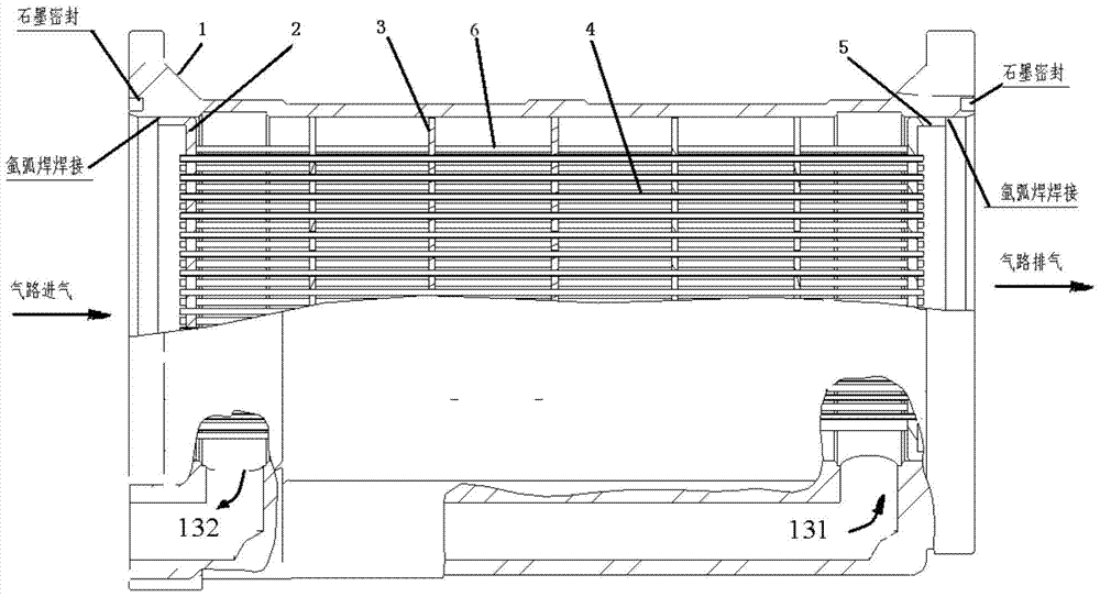
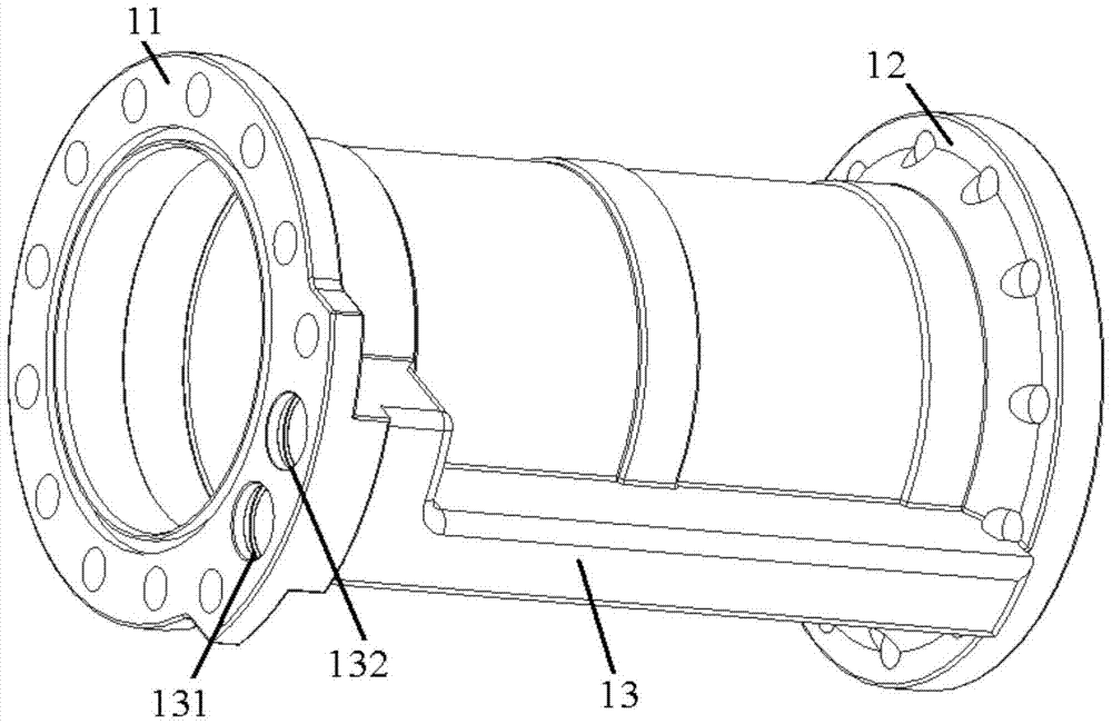
[0046] The hydrogen cooler of the present invention adopts an integrated stainless steel tubular structure, figure 1 It is a structural schematic diagram of the cooler of the present invention, which is mainly composed of a stainless steel shell 1 , a front end plate 2 , a baffle plate 3 , a tube bundle 4 , a rear end plate 5 , and a support rod 6 .

[0047]The stainless steel shell 1 is a load-bearing part, and is screwed to the main structure of the servo mechanism through flanges at both ends. All the capillary tube bundles 4 pass through the baffle plate 3, the front end plate 2 and the rear end plate 5, and are welded with the front end plate 2 and the rear end plate 5 by brazing; the front end plate 2 and the stainless steel shell 1 are welded by argon arc welding; the rear end Plate 5 and stainless steel shell 1 are welded by argon arc welding.

[0048] Both ends of the stainless steel shell 1 and the main body of the servo mechanism are sealed with flexible graphite; ...


PUM


Abstract

The invention relates to an in-line tube cooler, in particular to a cooler for an electro-hydraulic servo mechanism and a cooling method. The cooler can be connected in series and embedded in the main structure of the electro-hydraulic servo mechanism to realize the working medium of the electro-hydraulic servo mechanism. The invention discloses oil cooling, which belongs to the technical field of electro-hydraulic servo mechanism cooling. The cooler includes a stainless steel housing, front end plates, baffles, tube bundles, rear end plates and support rods. The low-temperature gas of the present invention is the gas after the servo mechanism performs work, which realizes the cooling of the hydraulic oil of the servo mechanism, does not need to introduce a cooling medium from the outside, and has high energy utilization; There are reinforcing ribs on the oil inlet channel and oil outlet channel, which makes the structure of the cooler compact, and the reinforcing ribs can be used as channels without additional pipeline channels and joint accessories, so that the weight reduction effect of the cooler is obvious.

Description

technical field [0001] The invention relates to an in-line tube cooler, in particular to a cooler for an electro-hydraulic servo mechanism and a cooling method. The cooler can be connected in series and embedded in the main structure of the electro-hydraulic servo mechanism to achieve The oil cooling belongs to the technical field of electro-hydraulic servo mechanism cooling. Background technique [0002] The energy conversion or work process of the energy components of the electro-hydraulic servo mechanism is accompanied by heat generation. The working time is short or the heat generation is small. Generally, the metal substrate of the servo mechanism is used to absorb heat and dissipate heat. When the working time is long and the heat generation is huge, measures must be taken to protect the servo. Mechanism for temperature control. [0003] The servo mechanism uses turbo pump energy. When the servo mechanism is working, the heating power exceeds 20kW. If the metal substr...

Claims


Application Information

Patent Timeline
Patent Type & Authority Patents(China)
IPC IPC(8): F15B21/04
Inventor 景光辉张晓莎朱成林吕凤实丁勇刘波
Owner BEIJING RES INST OF PRECISE MECHATRONICS CONTROLS
Why Eureka
Eureka Blog
Learn More