Temperature control method of hydrogen catalysis combustor

A temperature control method and catalytic burner technology, which are applied to combustion methods, gas fuel burners, burners, etc., can solve the problems of reactor temperature fluctuation, inability to start catalytic combustion reaction, system instability, etc., and achieve low cost, The effect of wide application and simple control technology

Inactive Publication Date: 2016-02-17
CHINA JILIANG UNIV
View PDF5 Cites 1 Cited by
  • Summary
  • Abstract
  • Description
  • Claims
  • Application Information

AI Technical Summary

Problems solved by technology

At the same time, hydrogen catalytic combustion is a process of surface reaction control, and the start of the catalytic combustion process requires a process. Therefore, the current method of frequently switching the mixed gas inlet valve to control the temperature of the reactor brings many disadvantages, such as the reactor temperature. The fluctuation will be very large, which will bring unstable factors to the system. At the same time, when the reactor is turned on, it will often happen that the catalytic combustion reaction cannot be started.

Method used


Image

  • Temperature control method of hydrogen catalysis combustor

Examples


Embodiment 1

[0023] A temperature control method for a hydrogen catalytic burner, characterized in that: the temperature control method for a hydrogen catalytic burner comprises:

[0024] 1) The data processor collects the outlet temperature of the hydrogen catalytic burner through a temperature sensor;

[0025] 2) The data processor records the temperature change of the hydrogen catalytic burner and compares it with the set value;

[0026] 3) According to the comparison result between the temperature of the catalytic burner and the set value, the data processor feeds back and adjusts the fuel-air ratio of hydrogen and air;

Embodiment 2

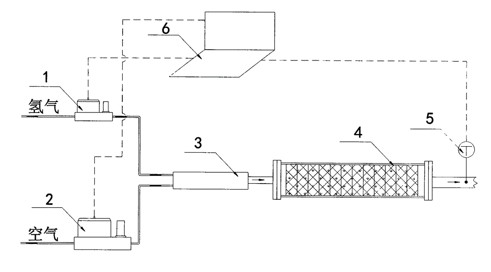
[0028] Set the temperature of the catalytic burner to 280°C (control target), when hydrogen and air with a fuel-to-air ratio of 8% enter the gas mixer 3 through the hydrogen flow controller 1 and the air flow controller 2 respectively, and then pass into the hydrogen catalytic combustion 4, the temperature sensor 5 detects a rapid rise in temperature. When the temperature rises to 280°C, the temperature sensor 5 detects that the temperature continues to rise, and the data processor 6 feeds back signals to the hydrogen flow controller 1 and the air flow controller 2 after comparison and calculation to adjust the fuel-air ratio to 6%. The sensor 5 detects that the temperature drops slowly; when the temperature drops to 260°C, the data processor 6 feeds back signals to the hydrogen flow controller 1 and the air flow controller 2 after comparison and calculation, and adjusts the fuel-air ratio to 7.2%, and finally catalyzes the combustion The temperature of the device was basicall...

Embodiment 3

[0030] Set the temperature of the catalytic burner to 350°C (control target), when hydrogen and air with a fuel-to-air ratio of 11% enter the gas mixer 3 through the hydrogen flow controller 1 and the air flow controller 2 respectively, and then pass into the hydrogen catalytic combustion 4, the temperature sensor 5 detects a rapid rise in temperature. When the temperature rises to 350°C, the temperature sensor 5 detects that the temperature continues to rise, and the data processor 6 feeds back signals to the hydrogen flow controller 1 and the air flow controller 2 after comparison and calculation to adjust the fuel-air ratio to 10%. The sensor 5 detects that the temperature drops slowly; when the temperature drops to 330°C, the data processor 6 feeds back the signal to the hydrogen flow controller 1 and the air flow controller 2 after comparison and calculation, adjusts the fuel-air ratio to 10.5%, and finally catalyzes the combustion The temperature of the device was basica...


PUM


Abstract

The invention relates to a temperature control method of a hydrogen catalysis combustor, and belongs to the technical field of hydrogen catalysis combustion. The control process of the temperature control method of the hydrogen catalysis combustor includes the steps that firstly, a data processor collects the outlet temperature of the hydrogen catalysis combustor through a temperature sensor; secondly, the data processor records the temperature change of the hydrogen catalysis combustor and compares the temperature change with a set value; and thirdly, the data processor conducts carries out feedback regulation on the fuel-air ratio of hydrogen and air according to the comparison result of the temperature of the catalysis combustor and the set value. The temperature control method has the beneficial effects of being simple in control technology, convenient to use, stable, reliable, economical, affordable, low in cost, wide in application range and the like, and can be widely used for temperature control of the hydrogen catalysis combustor.

Description

technical field [0001] The invention belongs to the technical field of hydrogen catalytic combustion, in particular to a method for controlling the temperature of a hydrogen catalytic burner. Background technique [0002] Hydrogen has many uses in daily life or industry. On the one hand, it is an energy carrier, which can be directly burned to generate heat for residential heating, and can also be used to generate electricity through fuel cells (FC) or hydrogen internal combustion engines (ICEs). For residential lighting or driving cars, etc., the whole utilization process does not produce greenhouse gases, so it is a kind of clean energy; on the other hand, due to its wide explosion limit and strong heat release effect, safety issues during use It is also a problem that needs to be solved urgently. [0003] Utilizing hydrogen catalytic combustion is an important energy recovery technology for many hydrogen-related processes and an important measure to improve system safety...

Claims


Application Information

Patent Timeline
IPC IPC(8): F23D14/60
Inventor 黄岳祥钮峰孙杏国
Owner CHINA JILIANG UNIV
Why Eureka
Try Eureka