Tensile test loading device and test method for unidirectional fiber reinforced composite materials perpendicular to the fiber direction

A technology of reinforced composite materials and unidirectional fibers, which is applied in the direction of measuring devices, analyzing materials, and testing the strength of materials by applying stable tension/pressure, which can solve the problems of uneven force on the clamping section, Problems such as the failure of the contact surface of the fixture to achieve the effect of ensuring accuracy, wide application range, and eliminating connection gaps

Active Publication Date: 2017-12-22
NANJING UNIV OF AERONAUTICS & ASTRONAUTICS
View PDF20 Cites 0 Cited by
  • Summary
  • Abstract
  • Description
  • Claims
  • Application Information

AI Technical Summary

Problems solved by technology

[0004] The tensile fixture disclosed in Chinese patent CN103018101A "A Fixture for High Temperature Tensile Testing of Ceramic Matrix Composite Materials" can be used for most structures of composite materials, but it is used for tensile strength of unidirectional fiber-reinforced composite materials perpendicular to the fiber direction. The specimen will fail at the contact surface of the grip during the tensile test
The fixture adopts bolt connection to clamp the sample, so the uneven force on the clamping section is prone to slipping
In addition, none of the technical solutions disclosed in the prior art involves the solution to the problem of eliminating the fit gap between the components of the combined fixture

Method used


Image

  • Tensile test loading device and test method for unidirectional fiber reinforced composite materials perpendicular to the fiber direction
  • Tensile test loading device and test method for unidirectional fiber reinforced composite materials perpendicular to the fiber direction
  • Tensile test loading device and test method for unidirectional fiber reinforced composite materials perpendicular to the fiber direction

Examples


no. 1 example

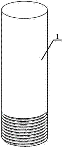
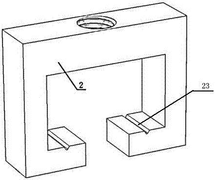
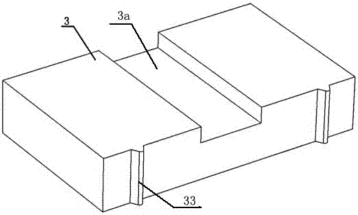
[0053] A tensile test loading device for unidirectional fiber-reinforced composite materials perpendicular to the fiber direction, including an upper clamping rod 1, a loading frame 2, a force transmission piece 3, a threaded connecting rod 5, a gap elimination nut 6, and a lower clamping rod 7; One end of the clamping rod 1 is provided with a right-handed thread, and the other end is a polished rod; one end of the lower clamping rod 7 is provided with a left-handed thread, and the other end is a polished rod; the loading frame 2 is two identical upper loading frame 21 and lower loading frame 22 , wherein the upper loading frame 21 is connected with the upper clamping rod 1, and the lower loading frame 22 is connected with the threaded connecting rod 5; A V-shaped positioning long groove with the same thickness as the loading frame 2 is symmetrically provided on the opening surface of the frame; the force transmission sheet 3 is provided with four identical pieces, which are re...

no. 2 example

[0068] Replace the unidirectional fiber-reinforced carbon / carbon composite strip-shaped tensile specimen in the first embodiment with a unidirectional fiber-reinforced resin-based composite material dog-bone tensile specimen, such as Figure 10 and Figure 11 shown. The parts not described are the same as the first embodiment.

no. 3 example

[0070] The unidirectional fiber-reinforced carbon / carbon composite strip tensile specimen in the first embodiment is replaced by the unidirectional fiber-reinforced ceramic matrix composite dovetail tensile specimen. Correspondingly, the groove 3a is as wide as the outside, Narrow dovetail trough on the inside, such as Figure 12 to Figure 14 shown. The parts not described are the same as the first embodiment.

[0071] The third embodiment improves the shape of the clamping part of the sample and the shape of the force transmission piece 3, so that the contact area between the sample and the force transmission piece 3 is larger. Wide and narrow inside, the sample is more difficult to come out, and the connection is firm.


PUM


Abstract

The invention discloses a loading device and method for testing the tension strength of a unidirectional fiber reinforced composite perpendicular to the fiber direction. The loading device comprises an upper clamping rod, a loading frame, a force transferring piece, a threaded connecting rod, a gap eliminating nut and a lower clamping rod. The force transferring piece comprises upper force transferring piece bodies and lower force transferring piece bodies, the upper force transferring piece bodies are pasted on the upper end of a unidirectional fiber reinforced composite test specimen, the lower force transferring piece bodies are pasted to the lower end of the unidirectional fiber reinforced composite test specimen, and fibers in the unidirectional fiber reinforced composite test specimen are perpendicular to the tension strength testing direction. The loading frame comprises an upper loading frame body and a lower loading frame body, the upper force transferring piece bodies are fixedly installed in the upper loading frame body, and the lower force transferring piece bodies are fixedly installed in the lower loading frame body. The upper clamping rod is fixedly connected with the upper loading frame body. The lower clamping rod is fixed to the lower loading frame body in a matched mode through the threaded connecting rod and the gap eliminating nut. The loading device has the advantages that damage, caused by clamping force of a tester, on the test specimen can be avoided, connecting gaps between clamp components can be eliminated, testing precision can be improved, and accurate alignment of the test specimen can be achieved.

Description

technical field [0001] The invention relates to the field of mechanical testing of composite materials, in particular to a tensile test loading device and a testing method for unidirectional fiber-reinforced composite materials perpendicular to the fiber direction. Background technique [0002] Fiber-reinforced composites have the advantages of high specific strength, high specific modulus, and good chemical stability, and are widely used in energy, military, and transportation fields. With the extensive application of fiber-reinforced composites, the testing methods of their mechanical properties have also received extensive attention. The mechanical performance parameters such as tensile strength, elastic modulus and Poisson's ratio of the material can be obtained through the tensile test of the fiber reinforced composite material, which has important guiding significance for the safe and reliable application of the composite material. [0003] Most of the tensile test me...

Claims


Application Information

Patent Timeline
Patent Type & Authority Patents(China)
IPC IPC(8): G01N3/08G01N3/04G01N3/02
Inventor 于国强宋迎东高希光薛建刚
Owner NANJING UNIV OF AERONAUTICS & ASTRONAUTICS
Why Eureka
Try Eureka