
System and method for measuring wind speed and wind direction

A wind speed wind direction, measurement system technology, applied in the direction of fluid speed measurement, speed/acceleration/shock measurement, measurement devices, etc., can solve the problems of not getting good results, incorrect data of the test unit, difficult to eliminate interference, etc., to achieve cost The effect of low cost, guaranteed accuracy and good cost advantage

Active Publication Date: 2016-02-17
SOUTHEAST UNIV
View PDF7 Cites 15 Cited by
  • Summary
  • Abstract
  • Description
  • Claims
  • Application Information

AI Technical Summary

Problems solved by technology

3) Even in the case of strictly parallel air flow, the upper and lower parallel plate structure itself is a kind of wind collecting structure, just like an airplane wing, its existence will change the flow of wind, so it may affect the measurement results. The above Although the three points can be improved by software correction, it is difficult to eliminate the interference caused by the change of wind direction.
[0004] In fact, many test methods currently used are disturbed by wind direction changes. At this time, a single test unit may give completely incorrect data. Even if multiple measurement units are used, it will also be due to the problem of accurate judgment of wind direction But good results cannot be obtained. Especially when the air flow direction is not strictly parallel to the horizontal plane, for example, there is a wind speed component perpendicular to the horizontal plane. Because the wind direction test system commonly used now also defaults to the air flow being parallel to the horizontal plane. .So it actually lacks an accurate reflection of the real wind direction. Therefore, generally speaking, the current wind speed and direction test system lacks systematic and careful consideration of this actual situation, and the results obtained can only reflect part of the actual situation. If To obtain comprehensive and detailed information, a new and different system needs to be constructed

Method used


Image

  • System and method for measuring wind speed and wind direction
  • System and method for measuring wind speed and wind direction
  • System and method for measuring wind speed and wind direction

Examples


Embodiment Construction

[0036] The present invention will be further described below in conjunction with the accompanying drawings.

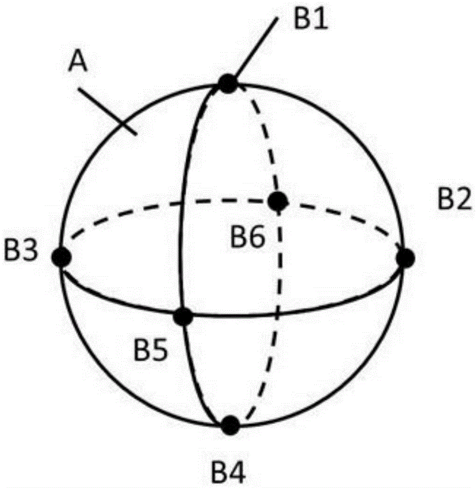
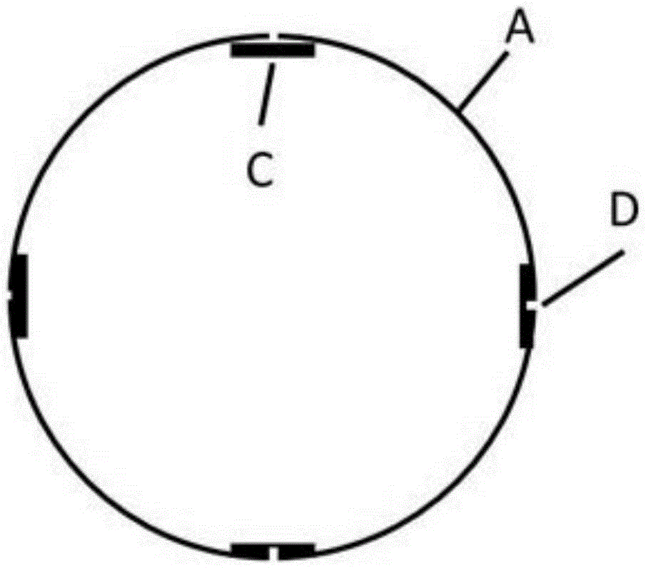
[0037] Such as figure 1 As shown, a measuring ball for measuring wind speed and direction includes a spherical shell with a smooth surface, 6 pressure measuring holes are evenly opened on the spherical shell, the diameter of the spherical shell is 100 mm, and the diameter of the pressure measuring holes is 1 mm. There is a pressure measuring hole at the intersection of three vertical circles with the center of the sphere as the center, and an air pressure sensor is arranged inside each pressure measuring hole; the air pressure sensor and the corresponding pressure measuring hole are sealed. Connect and isolate the pressure measuring hole from the inner cavity of the spherical shell, such as figure 2 shown.

[0038] When the direction of air flow is along the connecting line of B5-B6 and is directed from B5 to B6, B1-B4 gives the same pressure, and the pressure is po...


PUM


Abstract

The invention provides a system for measuring wind speed and wind direction. The system comprises a spherical shell which is smooth-faced, wherein 6 pressure measuring holes are formed in the spherical shell uniformly; one pressure sensor is arranged at the inner side of the each pressure measuring hole; and each pressure sensor is in sealed connection with the corresponding pressure measuring hole so as to isolate the pressure measuring hole from an inner chamber of the spherical shell. The system and method for measuring wind speed and wind direction utilize the integrated and spherical surface uniform distribution type sensing system, and can realize accurate determination of wind speed and wind direction by means of the technology that tests pressure intensity distribution of different points on the surface of the sphere in an air flow field.

Description

technical field [0001] The invention relates to an integrated wind speed and wind direction testing method, belonging to the technical field of high-performance components and equipment manufacturing. Background technique [0002] The test or measurement of wind speed and wind direction is a topic closely related to meteorology, transportation, agriculture and other fields. Conventionally, there are many methods of testing wind speed and wind direction currently available on the market, such as the hot wire method, that is, using a heating filament as a sensitive element, and judging the wind speed by sensing the difference in heat dissipation at different wind speeds the size of. Since its heat dissipation is also related to the ambient temperature, it is necessary to consider the correction of the ambient temperature to obtain a more accurate wind speed, but its ability to judge the wind direction is relatively poor; the method of rotating the wind measuring bowl or the w...

Claims


Application Information

Patent Timeline
Patent Type & Authority Applications(China)
IPC IPC(8): G01P5/02G01P13/02
Inventor 万能
Owner SOUTHEAST UNIV
Learn More