bidirectional optical transmission subassembly

A sub-component, two-way optical technology, applied in the field of optical communication components, can solve the problems of multi-device space, multi-device slots, occupancy, etc., and achieve high data transmission volume, reduce volume, and effectively use space.

Active Publication Date: 2017-03-01
APPLIED OPTOELECTRONICS
View PDF6 Cites 0 Cited by
  • Summary
  • Abstract
  • Description
  • Claims
  • Application Information

AI Technical Summary

Problems solved by technology

However, this method requires multiple independent optical transceiver modules, which will take up more equipment slots, thus requiring more equipment space

Method used


Image

  • bidirectional optical transmission subassembly
  • bidirectional optical transmission subassembly
  • bidirectional optical transmission subassembly

Examples


Embodiment Construction

[0070] The detailed features and advantages of the present invention are described in detail below in the embodiments, the content of which is sufficient to enable any person familiar with the relevant art to understand the technical content of the present invention and implement it accordingly, and according to the content disclosed in this specification, the scope of claims and the accompanying drawings , anyone skilled in the relevant art can easily understand the related objects and advantages of the present invention. The following examples are to further describe the viewpoints of the present invention in detail, but not to limit the scope of the present invention in any way.

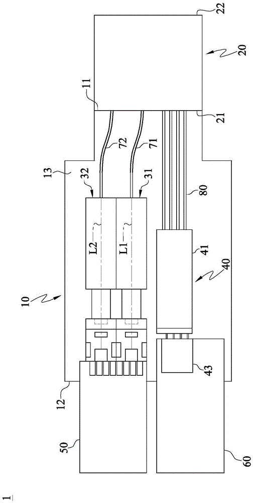
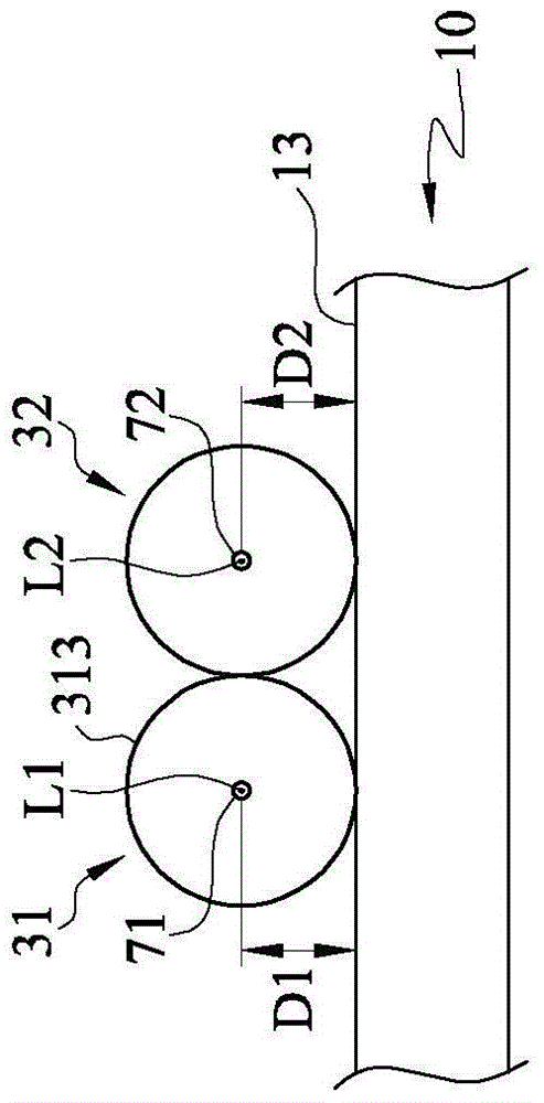
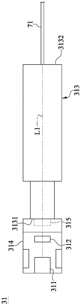
[0071] The invention discloses an optical fiber communication device, which is a bidirectional optical sub-assembly (BOSA, Bidirectional optical sub-assembly), one end of which can be connected to an optical fiber, and the other end is electrically connected to an electronic device. The bidirectio...


PUM


Abstract

A bidirectional light transmission subassembly comprises a substrate, a multi-core connecting piece, a first light output module, a second light output module, a light reception module, an output circuit board and a reception circuit board. The substrate includes a first side, a second side and a bearing surface. The multi-core connecting piece is placed at the first side. The first light output module is placed on the substrate and coupled to the multi-core connecting piece via an output fiber. The second light output module is placed at the bearing surface and coupled to the multi-core connecting piece via another output fiber. The distance from the optical axis of the first output module to the bearing surface is the same with that from the optical axis of the second output module to the bearing surface, and the optical axis of the first output module is close to that of the second output module. The light reception module is placed on the substrate and coupled to the multi-core connecting piece via a reception fiber. The output circuit board is placed at the second side and electrically connected with the first and second light output modules. The reception circuit board is placed at the second side and electrically connected with the light reception module.

Description

technical field [0001] The invention relates to an optical communication component, in particular to a bidirectional optical transmission subassembly. Background technique [0002] At present, the optical fiber network that has been widely used in long-distance backbone networks in many countries around the world is mostly systems that provide 2.5Gbps (Giga bit per second), 5Gbps, or 10Gbps. Among them, optical transceiver devices play an important role. Furthermore, with the advancement of technology, optical transceiver devices have developed from the earlier 155Mbps, 622Mbps, 1Gbps to the current popular 10Gbps, 25Gbps, 40Gbps. In the near future, speeds above 100Gbps are expected to be achieved. [0003] However, the data transmission capacity of optical fiber communication devices has gradually become insufficient. Therefore, there has been a trend to further increase the data transmission capacity of the optical fiber communication device. [0004] Under the existi...

Claims


Application Information

Patent Timeline
Patent Type & Authority Patents(China)
IPC IPC(8): G02B6/43
Inventor 苏立杰林昌省罗建洪聶鹏
Owner APPLIED OPTOELECTRONICS
Why Eureka
Try Eureka