Circumferentially-feeding and circumferentially-discharging flow assisting type sedimentation basin

A sedimentation tank and auxiliary flow technology, which is applied to the feeding/discharging device of the settling tank, the settling tank, etc., can solve the problems of large floor area and limited construction site

Active Publication Date: 2016-02-24
THUNIP CORP LTD +1
View PDF8 Cites 3 Cited by
  • Summary
  • Abstract
  • Description
  • Claims
  • Application Information

AI Technical Summary

Problems solved by technology

[0006] The purpose of the present invention is to provide a settling tank with auxiliary flow in and out of the week, which can reduce the occupied area without reducing the amount of sewage treatment, so as to greatly save land and solve the problem of auxiliary flow in and out of the week. The type sedimentation tank occupies a large area and the construction site is limited

Method used


Image

  • Circumferentially-feeding and circumferentially-discharging flow assisting type sedimentation basin
  • Circumferentially-feeding and circumferentially-discharging flow assisting type sedimentation basin
  • Circumferentially-feeding and circumferentially-discharging flow assisting type sedimentation basin

Examples


Embodiment 1

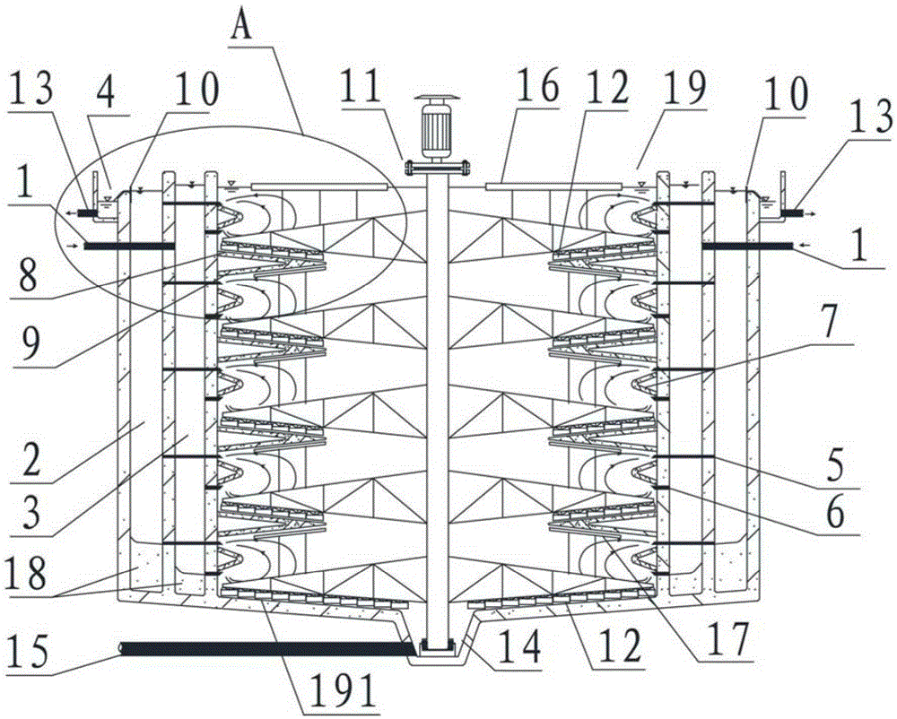
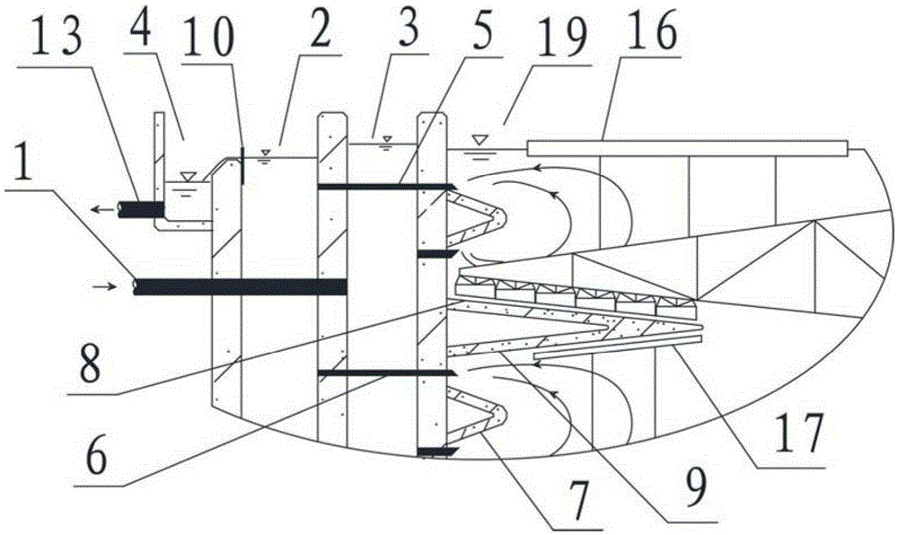
[0031] Such as figure 1 and 2As shown, the week-in and week-out auxiliary flow sedimentation tank provided by the embodiment of the present invention includes a tank body 19, a water distribution annular well 3, a water collection annular well 2 and a mud scraper and slag discharger 11, and the water distribution annular well 3 is arranged around the pool Outside the body 19, the water receiving annular well 2 rings are arranged on the outside of the water distribution annular well 3. Preferably, the diameter of the pool body 19 is 20m-30m, and the specific size is determined according to the calculation of the water volume, wherein the upper surface of the bottom of the pool body 19 is the bottom of the pool A sludge collection surface 191, the central area of ​​the sludge collection surface 191 at the bottom of the pool is provided with a sludge bucket 14, and the bottom of the sludge bucket 14 is provided with a sludge discharge pipe 15 communicating with the outside of the...

Embodiment 2

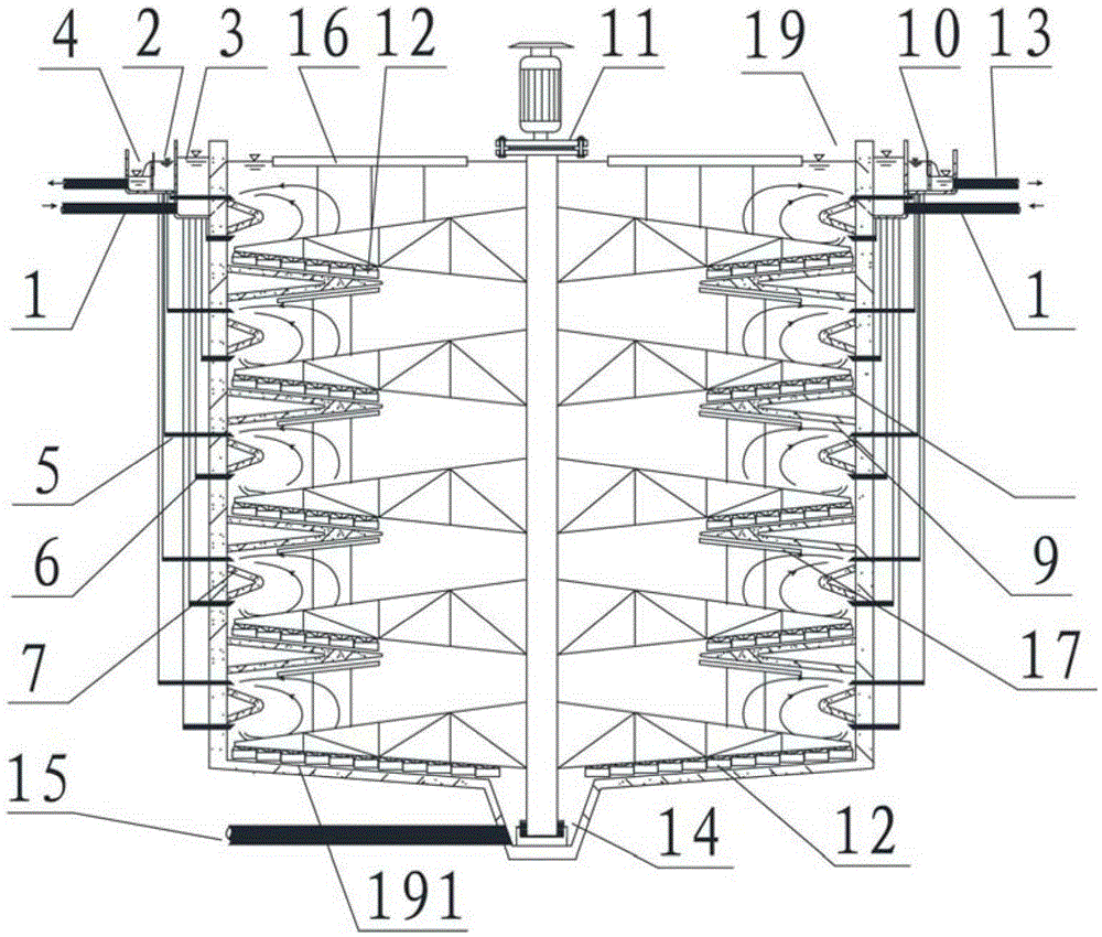
[0056] Such as image 3 As shown, the second embodiment is basically the same as the first embodiment, and the similarities will not be repeated. The difference is that the depths of the water inlet and distribution annular well 3 and the water collection annular well 2 are reduced so that they are only arranged in the pool body 19 The top position is in the shape of a channel, and the pipes with the same diameter as the water inlet distribution pipe 6 and the water collection pipe 6 are used at the bottom to connect with the corresponding water inlet distribution pipe 6 and the water collection pipe 6 respectively, so as to reduce the amount of reinforced concrete in the pool body , reduce the cost of the tank body, and can further reduce the area of ​​the sedimentation tank and save the area occupied by the sedimentation tank. This embodiment is especially suitable for regions where the climate is warm and does not freeze in winter.

[0057] In summary, the week-in and week...


PUM

PropertyMeasurementUnit
diameteraaaaaaaaaa

Abstract

The invention relates to the technical field of sewage processing facilities, in particular to a circumferentially-feeding and circumferentially-discharging flow assisting type sedimentation basin. The sedimentation basin comprises a basin body, a water distribution annular well, a water collection annular well and a mud scraping and residue discharging machine. The water distribution annular well is arranged outside the basin body in a surrounding mode. The water collection annular well is arranged outside the water distribution annular well in a surrounding mode. A sludge hopper is arranged at the center of the bottom of the basin body. Multiple layers of sedimentation plates are arranged on the side wall of the basin body in the vertical direction in a surrounding mode, and therefore the sedimentation area is enlarged, the occupied area is greatly reduced under the condition that the processing amount is ensured, guide plates are arranged on the portions, in all sedimentation layers, of the basin body in the circumferential direction in a surrounding mode, a plurality of water collection pipes evenly arranged around the basin body are located on the upper sides of the guide plates respectively, a plurality of water inlet and water distribution pipes evenly arranged around the basin body are located on the lower sides of the guide plates respectively, the water inlet and water distribution amounts and the water outlet amounts between all the sedimentation layers in the basin body are kept consistent, and therefore it is ensured that water flow in all the sedimentation layers is uniform.

Description

technical field [0001] The invention relates to the technical field of sewage treatment facilities, in particular to a secondary-flow sedimentation tank that enters and exits around. Background technique [0002] Sedimentation tank is the main component of activated sludge sewage treatment technology. It is generally used to settle suspended solids or activated sludge in sewage to achieve the purpose of clarifying water quality. The circular auxiliary flow sedimentation tank is a commonly used sedimentation tank shape in large and medium-sized sewage treatment facilities. Its main advantages are that the flow state of the water in the tank is evenly distributed, and the sedimentation performance is good. Section, the water flow per unit width is small, so as to ensure that the water has a small flow rate when it is close to the water outlet section, and fully ensure that the effluent water is as little as possible to entrain suspended solids or activated sludge flocs. The Z...

Claims


Application Information

Patent Timeline
Patent Type & Authority Applications(China)
IPC IPC(8): B01D21/02B01D21/24
Inventor 王旭李星文周丽颖
Owner THUNIP CORP LTD
Why Eureka
Try Eureka