Rolling mill and driving unit thereof

A kind of unit, rolling mill technology

Inactive Publication Date: 2016-02-24
CHONGQING MAITUO TECH CO LTD
View PDF6 Cites 0 Cited by
  • Summary
  • Abstract
  • Description
  • Claims
  • Application Information

AI Technical Summary

Problems solved by technology

[0004] However, this method results in a huge power of the main motor, which greatly increases the investment and maintenance costs; in addition, because the transmission chain is too long, the no-load power even reaches about thousands of kilowatts, resulting in a huge loss of energy consumption, which is not in line with the current energy saving and reduction requirements. platoon needs

Method used


Image

  • Rolling mill and driving unit thereof
  • Rolling mill and driving unit thereof

Examples


Embodiment Construction

[0021] The invention discloses a rolling mill and a transmission unit thereof, which have low investment, maintenance and use costs.

[0022] The following will clearly and completely describe the technical solutions in the embodiments of the present invention with reference to the accompanying drawings in the embodiments of the present invention. Obviously, the described embodiments are only some, not all, embodiments of the present invention. Based on the embodiments of the present invention, all other embodiments obtained by persons of ordinary skill in the art without making creative efforts belong to the protection scope of the present invention.

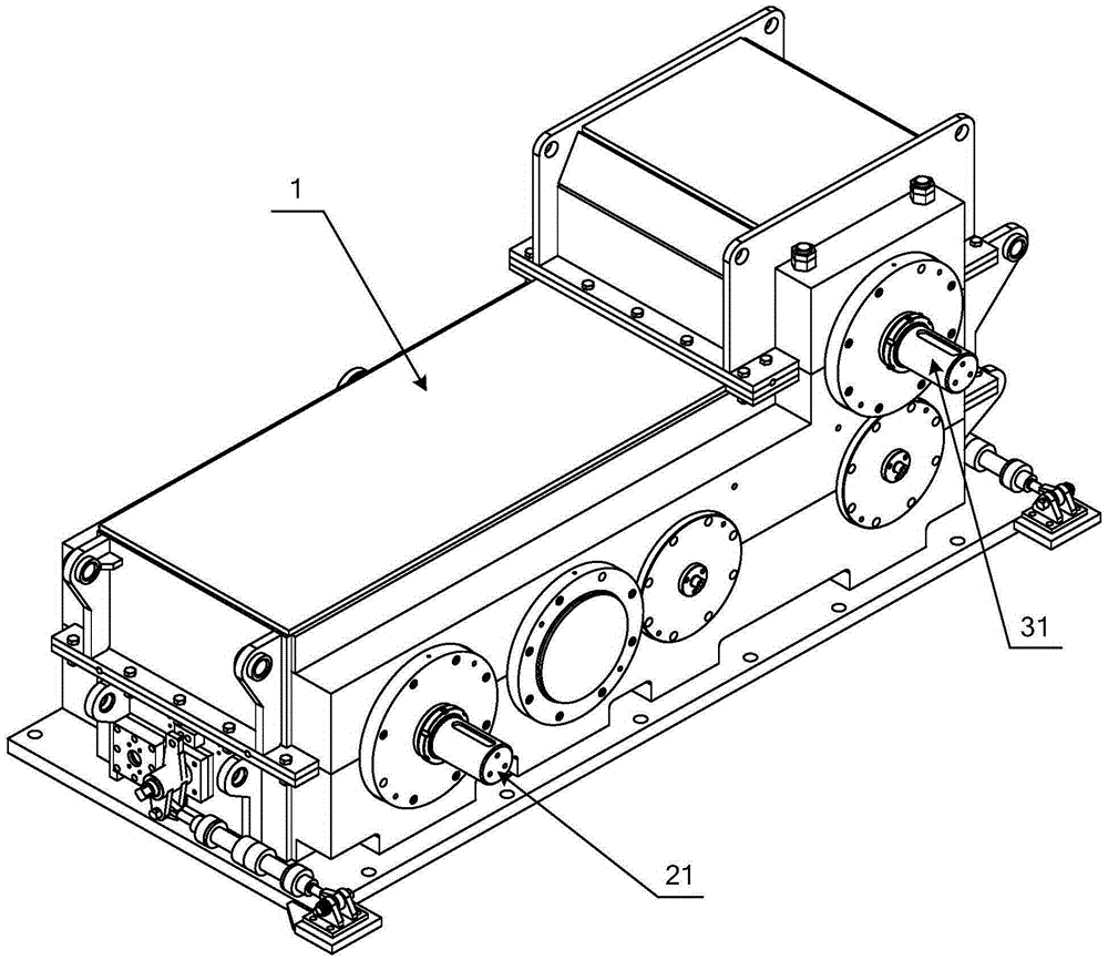
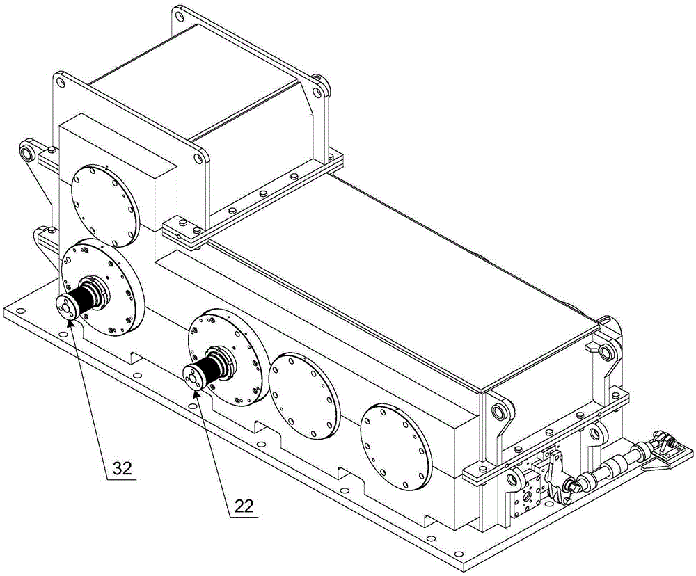
[0023] see figure 1 and figure 2 , figure 1 A schematic structural diagram of the input side of the gearbox provided by the embodiment of the present invention; figure 2 It is a schematic structural diagram of the output side of the gearbox provided by the embodiment of the present invention.

[0024] The rolling mill tra...


PUM


Abstract

The invention discloses a rolling mill and a driving unit thereof. The driving way of each roller is changed from the existing centralized driving to independent driving, so that gear driving pairs of gear shift mechanisms are reduced, the route of a driving chain becomes short, the driving efficiency is increased, and the no-load power is small; and each roller can be independently driven by a power mechanism with low power, so that expenses are greatly reduced, and the investment as well as using and maintaining costs are reduced. In addition, the independent driving way is adopted, the plurality of power mechanisms can also be controlled through speed regulation, so that the output rotating speeds form a flexible speed ratio relationship, but not a fixed speed ratio of racks of rolling mills with centralized driving ways. Meanwhile, the plurality of gear shift mechanisms are arranged in the same gearbox, and compared with a way of respectively arranging the plurality of gear shift mechanisms in different gearboxes, the way of arranging the plurality of gear shift mechanisms in the same gearbox has the advantages that the distance among the output shafts of the gear shift mechanisms is shortened, and furthermore, the rolling process requirement on a small spacing among roller boxes on the rolling mill is met, and the rolling quality is improved; in addition, vibration can be effectively reduced, installation is conveniently realized, the space occupied by equipment becomes small, and requirements on a workshop are lowered.

Description

technical field [0001] The invention relates to the technical field of steel rolling equipment, in particular to a rolling mill and a transmission unit thereof. Background technique [0002] As the main equipment on the steel hot rolling production line, the rolling mill is used to roll the blank into shape. [0003] At present, due to the needs of the process, the rolls on multiple racks are usually driven by centralized transmission, that is, a large main motor distributes power to each rack through a long shaft, and then the gears in each rack distribute There is a different but fixed speed ratio. [0004] However, this method results in a huge power of the main motor, which greatly increases the investment and maintenance costs; in addition, because the transmission chain is too long, the no-load power even reaches about thousands of kilowatts, resulting in a huge loss of energy consumption, which is not in line with the current energy saving and reduction requirements....

Claims


Application Information

Patent Timeline
IPC IPC(8): B21B35/12
CPCB21B35/12
Inventor 唐辉
Owner CHONGQING MAITUO TECH CO LTD
Why Eureka
Try Eureka