Screw tightening machine capable of preventing screw from being brought up

A screw tightening machine and belt lifting technology, which is applied in metal processing, metal processing equipment, manufacturing tools, etc., can solve problems such as stability influence, limited application occasions, and increased control difficulty

Inactive Publication Date: 2016-02-24
SHANGHAI WORKPOWER TELECOM TECH
View PDF10 Cites 25 Cited by
  • Summary
  • Abstract
  • Description
  • Claims
  • Application Information

AI Technical Summary

Problems solved by technology

There is no special anti-screw lifting device, the product may be lifted during use, and the stability may be affected in some applications
After the introduction of a single-axis manipulator, not only the cost increases, but also the difficulty of control increases accordingly; the patent document with the publication number CN103639691A discloses a machine tool component for assembly, including a base, a vertical column perpendicular to the base, a sliding plate, Fixing plate, cylinder, screwdriver and top cover
This patent also does not contain the anti-screw lifting device of the product, which limits its application occasions
The problem is that if the screw tightening machine directly touches the product, it will produce indentations on the surface of the product. If it does not directly touch the product, it is necessary to prevent the hidden danger of the product and the screw being carried by the batch head.

Method used


Image

  • Screw tightening machine capable of preventing screw from being brought up
  • Screw tightening machine capable of preventing screw from being brought up
  • Screw tightening machine capable of preventing screw from being brought up

Examples


Embodiment

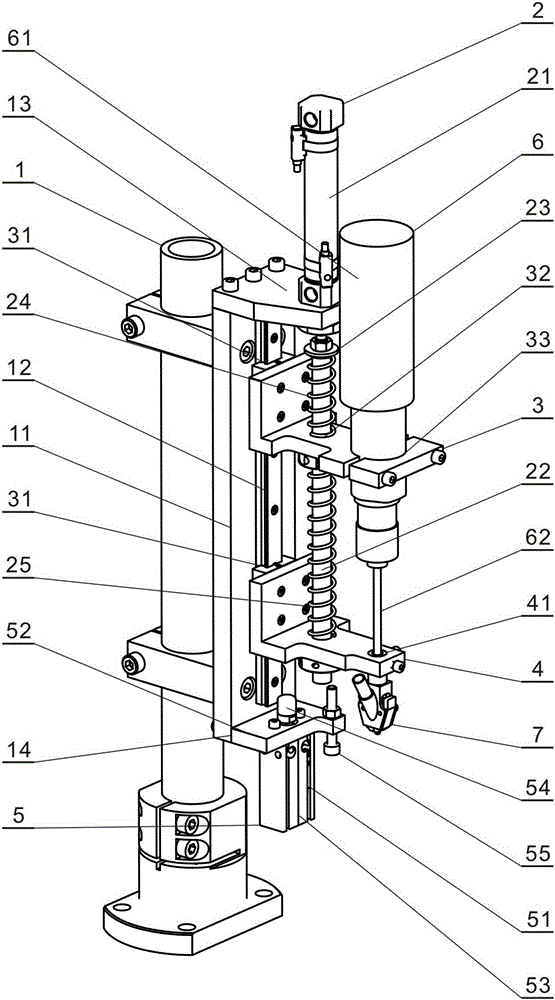
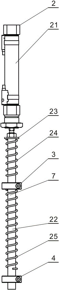
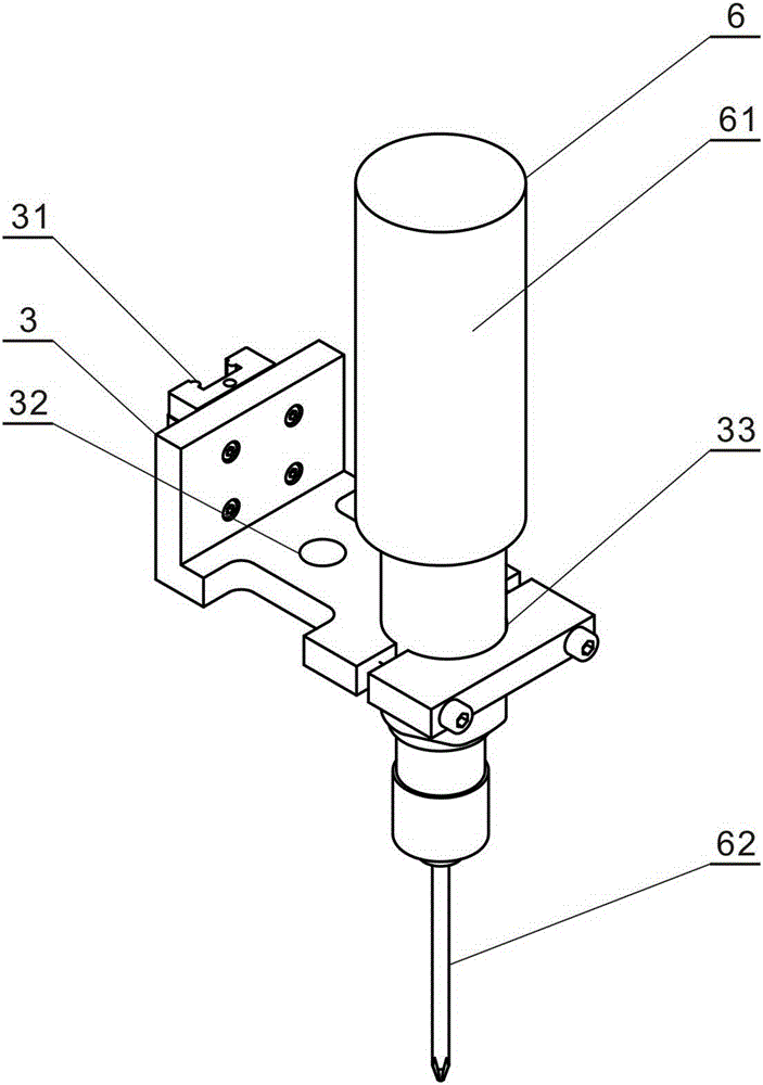
[0022] refer to figure 1 , figure 2 , Figure 7 , Figure 8 , the present invention adopts the PLC program control system to control the working procedures of each component in real time. The main points of work of the present invention are that when the batch knife 62 tightens the screw 9 on the product, the main cylinder 21 of the feed mechanism 2 drives the electric batch 61 of the upper slider 3, so as to maintain a stable axial contact between the batch knife 62 and the screw 9 When the batch knife 62 exits the screw 9, the jacking mechanism 5 drives the lower slider 4, prompting the batch head 7 to quickly disengage from the screw 9, and at the same time when the screw tightening work is completed, the hidden danger of the screw 9 being carried by the batch head is eliminated , to realize the non-contact pressure assembly between the present invention and the product 8.

[0023] Taking screw 9 screwed into the connector to implement product assembly as an example, t...


PUM


Abstract

The invention discloses a screw tightening machine capable of preventing a screw from being brought up. The screw tightening machine comprises a support, a feed mechanism, an upper slide block, a lower slide block, a pushing-up mechanism, an electric screwdriver assembly and a screwdriver head. The support is provided with an air cylinder seat and a pushing-up mechanism seat. The feed mechanism is composed of a main air cylinder and a feed rod. The upper slide block and the lower slide block are arranged on the support. The feed rod of the feed mechanism penetrates through the upper slide block and the lower slide block sequentially. The pushing-up mechanism is arranged on the pushing-up mechanism seat. The screwdriver head is arranged on the lower slide block. The electric screwdriver assembly is arranged on the upper slide block. The feed mechanism and the pushing-up mechanism are adopted for the screw tightening machine, so that when the screw is tightened through a screwdriver, stable axial contact force between the screwdriver and the screw is maintained. When the screwdriver retreats from the screw, the pushing-up mechanism makes the screwdriver head leave the screw fast, so that the hidden trouble that the screw is brought up by the screwdriver head is avoided completely. The screw tightening machine has the advantages of being contactless, easy to control and high in efficiency.

Description

technical field [0001] The invention relates to screw assembly in the technical field of automatic assembly, in particular to a screw tightening machine for preventing screws from being lifted. Background technique [0002] The screw tightening technology in the automated assembly production line is widely used in various occasions that require threaded connections. To tighten a screw, it involves screw feeding mechanism, screw tightening mechanism, PLC program control system, torque sensor and implementation monitoring system. The screw tightening mechanism is mostly realized by a single-axis manipulator with a single-cylinder locking mechanism, which is costly and difficult to control. In addition, under normal circumstances, when screwing in small screws or products, the screw tightening mechanism will be equipped with a workpiece pressing mechanism as an aid to prevent the screw and the product from being lifted up when the tightening mechanism is retracted. However, th...

Claims


Application Information

Patent Timeline
Patent Type & Authority Applications(China)
IPC IPC(8): B23P19/06
CPCB23P19/06
Inventor 刘志奎唐动刘林琳金先伦
Owner SHANGHAI WORKPOWER TELECOM TECH
Why Eureka
Try Eureka