
Tire crusher

A technology of tire powder and tires, which is applied in the direction of mechanical material recovery, recycling technology, plastic recycling, etc., can solve the problems of rubber blocks not being discharged from the circular screen in time, damage to the reducer and other components, and easy damage to the cutter, etc., to achieve The time used is short, the power requirement is not high, and the effect of noise generation is small

Active Publication Date: 2016-02-24
上海孚祥生态环保科技股份有限公司
View PDF7 Cites 11 Cited by
  • Summary
  • Abstract
  • Description
  • Claims
  • Application Information

AI Technical Summary

Problems solved by technology

The disadvantages of the shredder that crushes waste tires into about 50×50mm at one time are: the machine is easy to jam, the output is low, the knives are easily damaged, and it is easy to cause damage to the reducer and other components
Because the force of the whole machine is proportional to the width of the cutterhead 50mm, and the diameter of the tire is 1200mm, then there must be 24 cutterheads (50×24=1200) in the length direction of the machine, and at the same time the shearing force There are 23 of them; the second reason is that if the waste tires are broken into rubber blocks of about 50×50mm in one crusher, the rubber blocks larger than 50×50mm will inevitably be discharged from the round screen in time, and the Superimposed and broken with other larger rubber blocks, resulting in dead corner jamming
Therefore, the power consumption is large (when there is no material discharged from the round screen, overlapping crushing is more likely to jam the machine and damage the cutter)

Method used


Image

  • Tire crusher

Examples


Embodiment Construction

[0022] Below in conjunction with accompanying drawing, the present invention is described in detail.

[0023] In order to make the object, technical solution and advantages of the invention clearer, the present invention will be further described in detail below in conjunction with the accompanying drawings and embodiments. It should be understood that the specific embodiments described here are only used to explain the present invention, not to limit the present invention.

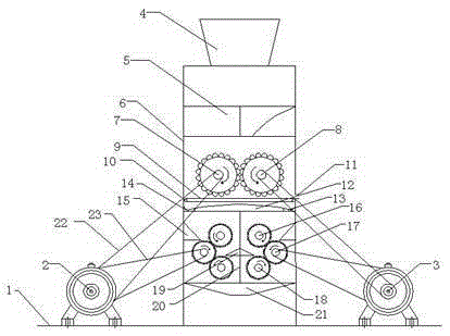
[0024] Such as figure 1As shown, a tire powder machine includes a base 1, a feed port 4, a tire pretreatment chamber 4 and a tire crushing cylinder 6, and a first driving motor 2 and a second driving motor are fixedly installed on both sides of the base 1. Motor 3, a tire crushing cylinder 6 is arranged between the first driving motor 2 and the second driving motor 3, the lower end of the tire crushing cylinder 6 is fixedly installed on the base 1, and the upper end of the tire crushing cylinder 6 is pro...


PUM


Abstract

The invention discloses a tire crusher which comprises a base, a feed opening, a tire pretreatment chamber and a tire crushing cylinder, wherein a first driving motor and a second driving motor are fixedly mounted on two sides of the base; the tire crushing cylinder is arranged between the first driving motor and the second driving motor; the lower end of the tire crushing cylinder is fixedly mounted on the base; the tire pretreatment chamber is arranged at the upper end of the tire crushing cylinder; the feed opening is formed in the upper end of the tire pretreatment chamber; a coarse crushing chamber is arranged at the upper part in the tire crushing cylinder; a crushing chamber is arranged in the lower part in the tire crushing cylinder; a first roll and a second roll are arranged in the coarse crushing chamber; the crushing chamber is divided into a first crushing chamber and a second crushing chamber; the first crushing chamber and the second crushing chamber are separated by a partition plate; and the first crushing chamber and the second crushing chamber adopt the same structure. Under certain cost control, the energy consumption is reduced, the production efficiency of the crusher is improved, and different grades of rubber blocks with a smaller crashing ratio are obtained.

Description

technical field [0001] The invention relates to the technical field of recycling waste tires, in particular to a tire shredder. Background technique [0002] In the recycling process of waste tires, it is necessary to break waste tires into small pieces of rubber. The waste tire coarse shredder currently in use is to put the whole waste tires on the whole tire conveyor and send them to LP-1200 for whole tire crushing The machine is crushed, through the repeated rotation of the circular screen and the repeated crushing of the cutter head, the size of the rubber block discharged from the screen is 50×50mm, and the rubber block of 50×50mm enters the next stage of the crusher for crushing. The disadvantages of the shredder that crushes waste tires into about 50×50mm at one time are: the machine is easy to jam, the output is low, the knives are easily damaged, and it is easy to cause damage to the reducer and other components. Because the force of the whole machine is proportion...

Claims


Application Information

Patent Timeline
IPC IPC(8): B29B17/04
CPCY02W30/52Y02W30/62
Inventor 肖勇
Owner 上海孚祥生态环保科技股份有限公司
Learn More