Energy recovery system and method for air suspension

An energy recovery and air suspension technology, applied in suspension, elastic suspension, control devices, etc., can solve problems such as low energy recovery efficiency, inability to adjust height, and inability to recover energy, so as to improve efficiency and ensure ride comfort. , the effect of improving energy recovery efficiency

Active Publication Date: 2017-06-27
吉客传动科技(苏州)有限公司
View PDF2 Cites 0 Cited by
  • Summary
  • Abstract
  • Description
  • Claims
  • Application Information

AI Technical Summary

Problems solved by technology

[0005] Most of the existing technologies use hydraulic shock absorbers for energy recovery. The patent application number is 201410615928.0 "Vibration Energy Recovery Device". This invention includes two parts: a vibration receiving device and an energy feeding device, which can recover both The energy of movement in one direction, and realize the damping effect; but this patent can only be applied to the hydraulic shock absorber, because the height cannot be adjusted, so the energy during the height adjustment cannot be recovered.
The patent application number is 201410721256.1 "A Vehicle Vibration Energy Recovery System and Control Method". The device can only be used for hydraulic shock absorbers, and energy recovery is performed during vibration, but the height cannot be adjusted, so the energy during height adjustment cannot be recovered, and the energy recovery efficiency is low

Method used


Image

  • Energy recovery system and method for air suspension
  • Energy recovery system and method for air suspension
  • Energy recovery system and method for air suspension

Examples


Embodiment approach

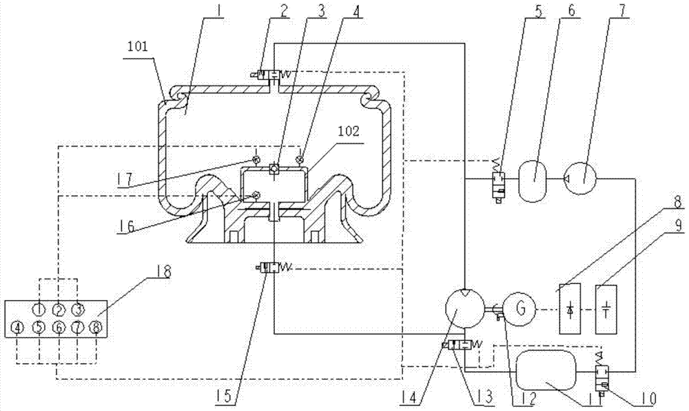
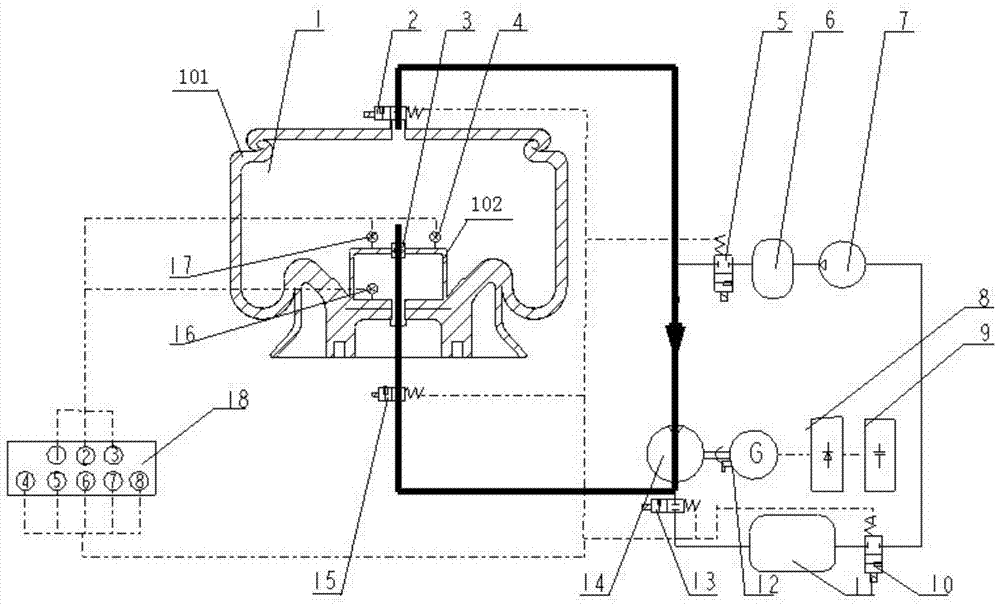
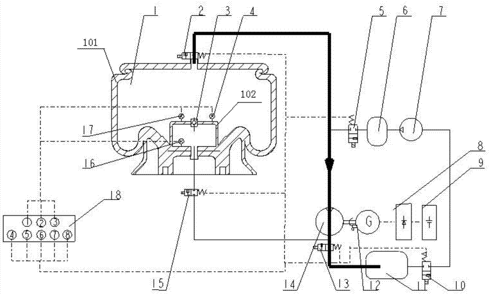
[0045] figure 1 Shown is an embodiment of the energy recovery system of the air suspension of the present invention, the energy recovery system of the air suspension includes an air spring shock absorber 1, a pneumatic actuator, a detection mechanism, a high-pressure storage tank 6, an air Compressor 7, low-pressure storage tank 11, air motor 14, power generation equipment and electronic control unit ECU18.

[0046] The pneumatic actuator includes a solenoid valve a2, a one-way valve 3, a solenoid valve b5, a solenoid valve c10, a solenoid valve d13 and a solenoid valve e15.

[0047] The pneumatic motor 14 is connected with the power generating equipment, and the power generating equipment includes a generator 12, a rectifier circuit 8 and a storage battery 9; the pneumatic motor 14 is connected with the generator 12, and the generator 12 passes through the rectifier The circuit 8 is electrically connected to the storage battery 9 .

[0048] The air spring shock absorber 1 i...


PUM


Abstract

The invention provides an energy recycling system and method for an air suspension. The energy recycling system comprises an air spring shock absorber, a pneumatic actuator, a detection mechanism, a high-pressure storage tank, an air compressor, a low-pressure storage tank, a pneumatic motor, a power generation device and an electric control unit (ECU). An air suspension system comprises the air spring shock absorber provided with a main air chamber and an auxiliary air chamber. A one-way valve is arranged at the joint of the main air chamber and the auxiliary air chamber. In the vibration process, the air pressure difference is generated between the main air chamber and the auxiliary air chamber through the one-way valve, gas flows to a power mechanism from the main air chamber, the power mechanism drives the power generation device to generate power, finally, the high-pressure airflow returns to the auxiliary air chamber of an air spring again, and therefore rigidity and damping of the air spring are ensured, and meanwhile energy consumed during vibration of a vehicle is recycled. When the height of a vehicle body is adjusted, an electromagnetic valve is controlled, the high-pressure gas is guided to flow through the power mechanism for power generation, and on the basis that the riding comfort is ensured, energy recycling efficiency is further improved.

Description

technical field [0001] The invention belongs to the technical field of automobile energy recovery, and in particular relates to an air suspension energy recovery system and a method thereof. Background technique [0002] With the deterioration of the environment and the shortage of energy, better energy saving and emission reduction on the basis of ensuring the original performance of the car has become the focus of the automotive industry. Although braking and vibration energy recovery technologies have developed, innovations in energy-saving technologies Breakthroughs and applications are still limited. [0003] The car will consume a lot of energy due to the vibration of the car during driving. Some studies have shown that the energy consumed by the vibration is far greater than the energy consumed by the car brake. If it can be effectively recovered, the cruising range of the electric car can be increased by 20%. ~30%, so if the energy consumed by the vibration of the c...

Claims


Application Information

Patent Timeline
Patent Type & Authority Patents(China)
IPC IPC(8): B60G13/14B60G17/052B60K25/10
CPCB60G13/14B60G17/052B60G2202/154B60G2300/60B60G2400/252B60G2400/51222B60K25/10B60K2025/106
Inventor 徐兴卢山峰陈龙孙晓强江浩斌汪若尘李贤波
Owner 吉客传动科技(苏州)有限公司
Why Eureka
Try Eureka