Partition power supply system for managing stray current at railway vehicle depot and control method

A subway depot, stray current technology, applied in vehicle components, power lines, transportation and packaging, etc., can solve problems such as arcing and ignition, and achieve the effect of aggravating leakage

Active Publication Date: 2016-02-24
SOUTHWEST JIAOTONG UNIV
View PDF6 Cites 20 Cited by
  • Summary
  • Abstract
  • Description
  • Claims
  • Application Information

AI Technical Summary

Problems solved by technology

[0004] Aiming at the problems existing in the above-mentioned double diode segmentation method, the purpose of the present invention is to block the stray current return path on the track between the depot and the main line, and control the stray current of the subway depot; Ignition at the insulation section, solve the problem of train pantograph crossing the catenary section, etc.; ensure the complete electrical isolation of the main line and the depot in the normal operation mode of the power supply system. Reliable electrical connection between the main line and the depot when the power stations need mutual support for power supply

Method used


Image

  • Partition power supply system for managing stray current at railway vehicle depot and control method
  • Partition power supply system for managing stray current at railway vehicle depot and control method
  • Partition power supply system for managing stray current at railway vehicle depot and control method

Examples


Embodiment Construction

[0026] The present invention will be described in detail below in conjunction with the accompanying drawings and embodiments.

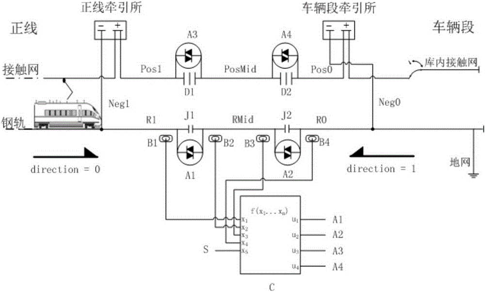
[0027] Such as figure 2As shown, the present invention includes insulation joint J (including J1, J2), catenary electrical segment D (including D1, D2), high-power DC thyristor switch A (including A1, A2, A3, A4), track axle counter B (including B1, B2, B3, B4), state identification control unit (C), depot power supply system operation status signal (S), characterized in that: two insulating joints J1, J2 are set between the depot and the main line , the distance between which is greater than 1.5 times the length of the train, cancel the one-way conduction device in parallel with J1 and J2 in the existing scheme, and connect A1 and A2 in parallel at both ends of J1 and J2 respectively, and the track area on the main line side of J1 is R1, J1, J2 The track area between them is RMid, and the track area on the J2 depot side is R0; catenary subsections ...


PUM


Abstract

The invention discloses a partition power supply system for managing a stray current at a railway vehicle depot and a control method. The partition power supply system and the control method are used for managing the stray current at the vehicle depot and ensure that vehicles can normally exit and enter the vehicle depot. The system comprises insulation joints J (comprising J1 and J2 ), contact line sections D (comprising D1 and D2 ), high-powered direct current thyristor switches A (comprising A1, A2, A3 and A4), track axle counters B (comprising B1, B2, B3 and B4 ), and a state identification control unit (C), wherein the two insulation joints (J1 and J2 ) are arranged between the vehicle depot and a main line, and the spacing is longer than 1.5 times of the length of the vehicle, the high-powered direct current thyristor switches (A1 and A2) are respectively connected with two ends of the first insulation joint J1 and the second insulation joint J2; the two track axle counters are respectively mounted beside tracks on two sides of the first insulation joint J1; the two track axle counters are respectively mounted beside tracks on two sides of the second insulation joint J2; output signals of the four track axle counters and the running state signals of the power supply system are connected with the state identification control unit; the state identification control unit controls the ordered switching on and the switching off of the four high-powered direct current thyristor switches in an output manner.

Description

technical field [0001] The invention belongs to a subway power supply system, in particular to a partition power supply control scheme for controlling stray currents in subway depots. Background technique [0002] Domestic subway traction power supply system adopts DC750V or DC1500V power supply system. In order to prevent the leakage of the traction return current to the earth and cause stray current corrosion, the main line rail is required to be insulated from the ground. In the subway depot, in order to control the rail-ground potential difference within a safe range and ensure the safety of maintenance personnel, the rails in the train inspection warehouse and washing garage are usually connected to the ground grid through integrated grounding electrodes, or rail potential limiters are installed on the upper rails in the warehouse. device. During normal operation, in order to prevent the current of the main line from leaking to the ground through the depot, insulation...

Claims


Application Information

Patent Timeline
Patent Type & Authority Applications(China)
IPC IPC(8): B60M3/00
Inventor 金安旭刘炜李群湛廖钧王沛沛许嘉轩刘瑞龙叶小雯许伶俐
Owner SOUTHWEST JIAOTONG UNIV
Why Eureka
Try Eureka