
friction torque converter

A torque converter and friction-type technology, which is applied in friction transmission devices, transmission devices, belts/chains/gears, etc., can solve the problems of reduced machine transmission efficiency, high cost, and headaches for users, and achieves simple structure, low cost, and The effect of strong reliability

Active Publication Date: 2018-11-16
TRANF TECH XIAMEN CO LTD
View PDF8 Cites 0 Cited by
  • Summary
  • Abstract
  • Description
  • Claims
  • Application Information

AI Technical Summary

Problems solved by technology

[0003] The main disadvantages of the hydraulic torque converter are complex structure, high cost, large mass, and due to the existence of hydraulic loss, the transmission efficiency of the machine is reduced, so the fuel economy and traction efficiency of the machine are reduced
To solve this problem, some cars have a lock-up clutch on the torque converter to improve the transmission efficiency, but the complicated system and expensive transmission parts have always been the main headaches for the repair market and users

Method used

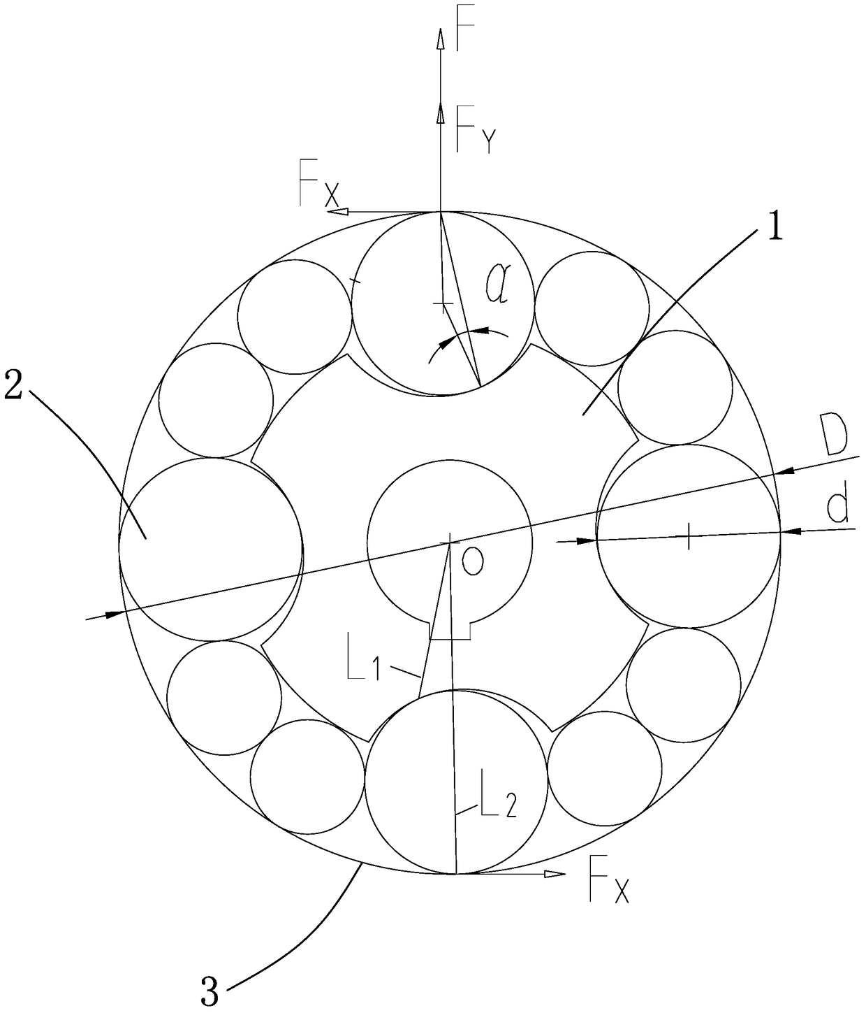
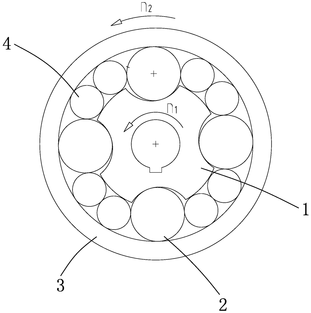

Image

  • friction torque converter
  • friction torque converter
  • friction torque converter

Examples


Embodiment

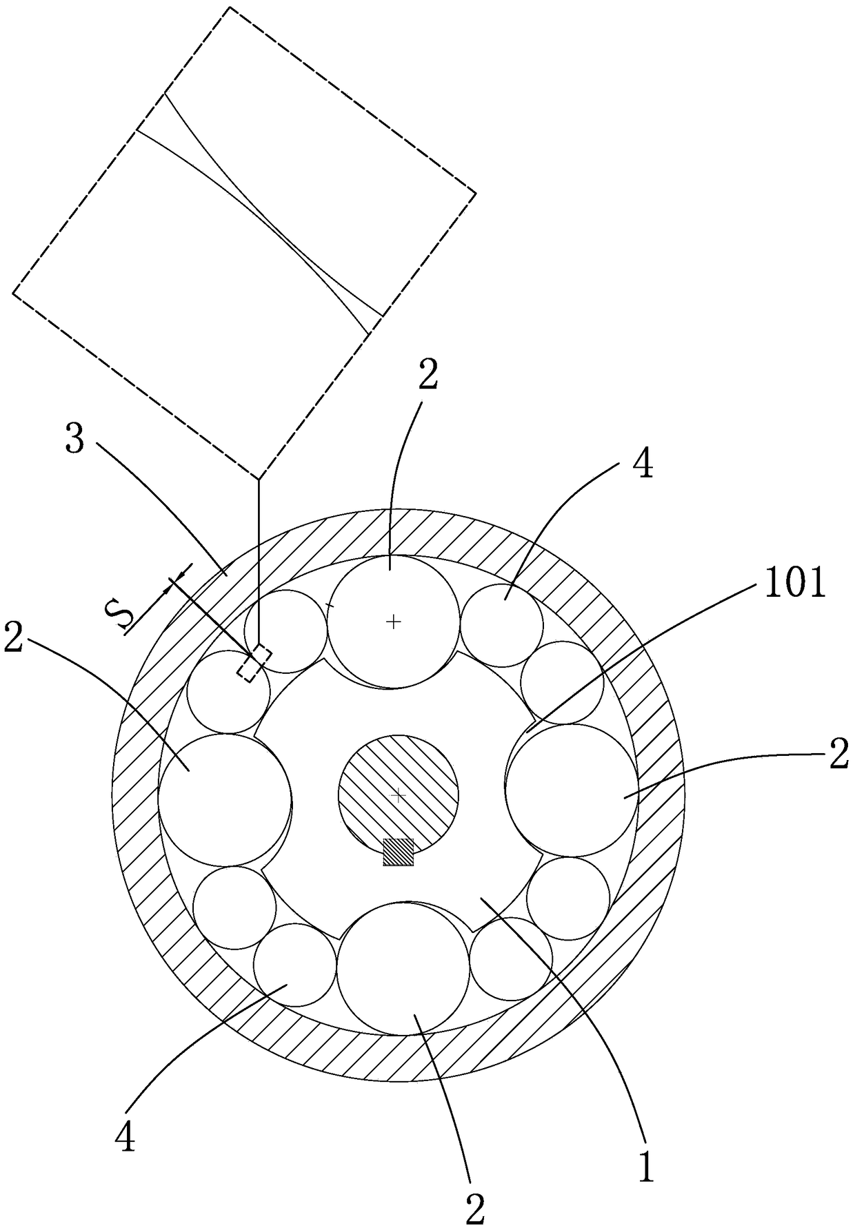
[0046] Example: see Figure 4 , a friction torque converter, including an inner ring 1, a large roller 2 and an outer ring 3, wherein:

[0047] The inner ring 1 is an input unit. At least two concave grooves 101 are evenly distributed on the peripheral side of the inner ring to form an inner ring cam. Each concave groove corresponds to a large roller. Figure 4 3 concave grooves and corresponding large rollers 2 are set in the middle;

[0048] The outer ring 3 is the output unit. The outer ring 3 is set outside the inner ring 1 and arranged coaxially with the inner ring 1. The inner peripheral surface of the outer ring 3 forms the inner raceway of the outer ring and is press-cut with each roller. Here The pressure cut means that the roller surface is pressed against the inner raceway of the outer ring. Since the roller and the outer ring are both arc-shaped surfaces, the two must be tangentially pressed;

[0049] The large roller 2 is arranged between the inner ring and the ...


PUM


Abstract

A friction type torque converter comprises an inner ring (1), large rolling columns (2), and an outer ring (3). The inner ring (1) is an input unit, and at least two grooves (101) being uniformly provided on a peripheral ring surface of the inner ring (1), each groove (101) corresponding to one large rolling column (2). The outer ring (3) is an output unit, the outer ring (3) sleeves the inner ring (1) and is coaxially arranged with the inner ring (1), and an outer ring inner rolling way is formed in an inner side circumferential surface of the outer ring (3) to fit each rolling column (2, 4). When a rotating speed and a load are changed, the rolling columns (2, 4) can adaptively work under the co - action of a centrifugal force and the inner ring (1) to finally realize locking output, automatic speed change and torque conversion of the friction type torque converter , so as to satisfy different applications.

Description

technical field [0001] The invention discloses a friction torque converter, which can realize a transmission system with stepless speed change and automatic torque change. Background technique [0002] At present, the most widely used torque converter is a hydraulic torque converter, also known as a torque converter, which is installed between the engine and the transmission, and uses hydraulic oil (ATF) as the working medium to transmit torque, change torque, change speed and The role of clutch. It is a non-rigid torque converter with liquid as the working medium. It is one of the types of hydraulic transmission and is widely used. The hydraulic torque converter is composed of pump wheel, turbine and guide wheel, etc. The hydraulic torque converter not only increases the torque of the engine, but also realizes the flexible connection between the engine and the automatic transmission, which effectively solves the problem of the engine The flameout problem can realize autom...

Claims


Application Information

Patent Timeline
Patent Type & Authority Patents(China)
IPC IPC(8): F16H15/50
CPCF16H15/50
Inventor 许水电李延福许涛许永建
Owner TRANF TECH XIAMEN CO LTD
Learn More