Printing-free light guide plate structure

A light guide plate, printing-free technology, applied in the direction of light guide, optics, optical components, etc., can solve the problems of difficult groove structure processing, complex processing technology of light guide plate, printing light guide ink dots, etc., to improve the brightness of light source, The effect of simple structure and high qualified rate of product quality

Inactive Publication Date: 2016-02-24
CHONGQING LINGCHUANGFU PHOTOELECTRIC TECH
View PDF9 Cites 0 Cited by
  • Summary
  • Abstract
  • Description
  • Claims
  • Application Information

AI Technical Summary

Problems solved by technology

[0004] The invention proposes a non-printing light guide plate structure, which solves the technical problems in the prior art that the light guide plate processing technology is complex, the groove structure is difficult to process, the light is uneven, and the dots of light guide ink need to be printed

Method used


Image

  • Printing-free light guide plate structure
  • Printing-free light guide plate structure
  • Printing-free light guide plate structure

Examples


Embodiment 1

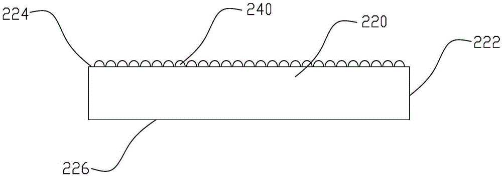
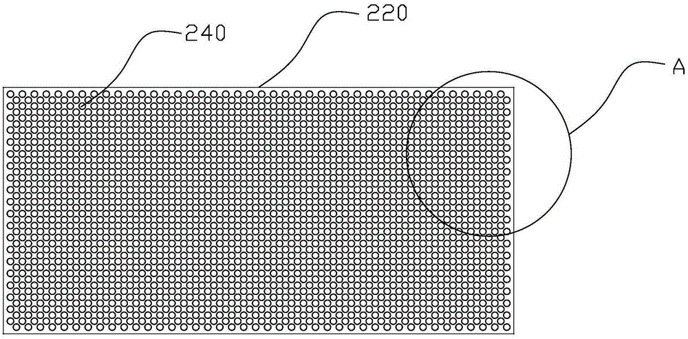
[0018] see Figure 1 to Figure 4 , a non-printing light guide plate structure, including a light guide plate body 220, the light guide plate body 220 includes a light incident surface 222 that guides a light beam 300 into the light guide plate body 220 and is located at the side of the light guide plate body 220, and guides the light beam 300 from the light guide plate body 220 The light exit surface 224 derived from the light plate body 220 and the bottom surface 226 opposite to the light exit surface 224, the bottom surface 226 is a smooth planar structure, a kind of non-printing light guide plate structure, including the light guide plate body, the light guide plate body 220 includes The light beam is introduced into the light guide plate body 220 and is located at the light incident surface 222 on the side of the light guide plate body 220, the light exit surface 224 that guides the light beam from the light guide plate body 220, and the bottom surface 226 opposite to the l...

Embodiment 2

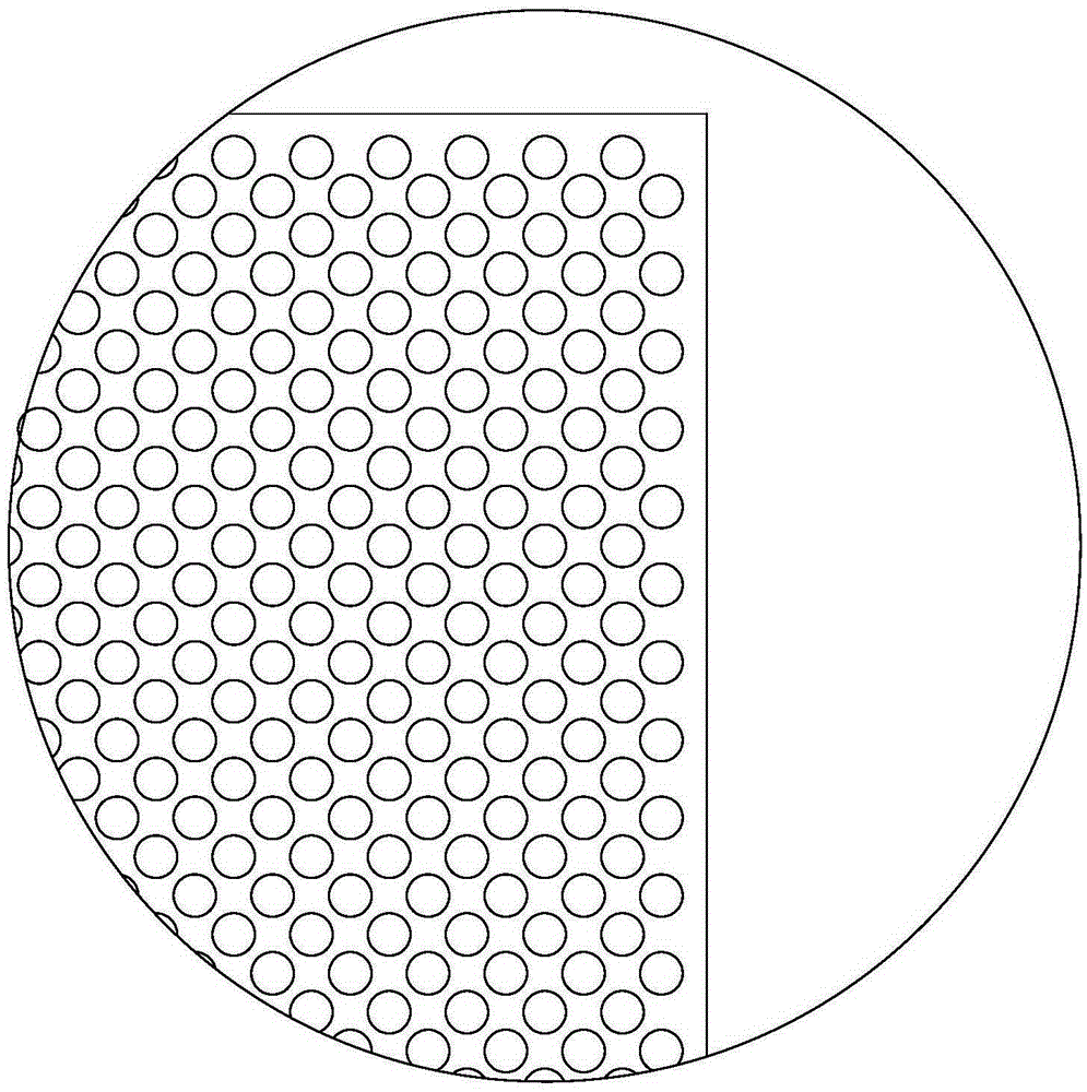
[0025] The structure of this embodiment is the same as that of Embodiment 1, except that the diameter of the spherical protrusion 240 is 190um, the height of the spherical protrusion 240 is 136.8um, and the distance between adjacent spherical protrusions 240 in each row and column is 237.5um, and the thickness of the light guide plate body 220 is 2.5mm.

Embodiment 3

[0027] The structure of this embodiment is the same as that of Embodiment 1, the difference is that the diameter of the spherical protrusion 240 is 200um, the height of the spherical protrusion 240 is 150um, and the distance between adjacent spherical protrusions 240 in each row is 250um. , the thickness of the light guide plate body 220 is 3.0 mm.


PUM


Abstract

The invention provides a printing-free light guide plate structure. The structure comprises a light guide plate body; the light guide plate body includes a light input surface, a light output surface and a bottom surface, wherein a light beam is guided into the light guide plate body via the light input surface, the light input surface is placed in the lateral portion of the light guide plate body, the light beam is guided out of the light guide plate body via the light output surface, and the bottom surface of a planar structure is opposite to the light output surface; multiple spherical projections which are molded with the light guide plate body in an integrated manner are arranged at the light output surface in an array, the spherical projections in the array are arranged in rows and columns in a staggered manner, and the spherical projections are made of a PMMA material; and the diameter of each spherical projection ranges from 180 to200 micron, the height of the spherical projection ranges from 135 to 150 micron, and the spacing between the adjacent spherical projections in each row / column ranges from 225 to 250 micron.

Description

technical field [0001] The invention relates to a non-printing light guide plate structure for a liquid crystal display. Background technique [0002] In recent years, with the colorization and enlargement of liquid crystal displays, their application fields are more extensive, such as notebooks, various desktop computers, and LCD TVs. Because the liquid crystal itself does not have luminous properties, therefore, the display effect is not achieved. It is necessary to provide a light source system as the light source of the display, such as a backlight module. The backlight module mainly includes a light guide plate, a light source, a reflector and one or more optical films. Among them, the light guide plate is an important component in the backlight module. It is used to guide the transmission direction of the light beam emitted from the light source, convert the line light source or point light source into a surface light source, and is used to display the brightness of th...

Claims


Application Information

Patent Timeline
Patent Type & Authority Applications(China)
IPC IPC(8): G02B6/00
CPCG02B6/0043
Inventor 郭志强程媛媛
Owner CHONGQING LINGCHUANGFU PHOTOELECTRIC TECH
Why Eureka
Try Eureka