
Sensing display device and shift register thereof

A technology of shift register and shift register, applied in static memory, static indicator, digital memory information and other directions, can solve the problems of component characteristic degradation and false output, and achieve the effect of preventing leakage

Active Publication Date: 2016-02-24
AU OPTRONICS CORP
View PDF5 Cites 15 Cited by
  • Summary
  • Abstract
  • Description
  • Claims
  • Application Information

AI Technical Summary

Problems solved by technology

[0005] The purpose of the present invention is to provide a sensing display device and its shift register to solve the technical problem that the drive transistor of the shift temporary storage circuit in the prior art is biased for a long time, which leads to the deterioration of the element characteristics and leads to the wrong output.

Method used


Image

  • Sensing display device and shift register thereof
  • Sensing display device and shift register thereof
  • Sensing display device and shift register thereof

Examples


Embodiment Construction

[0042] The following examples are described in detail with reference to the accompanying drawings, but the provided embodiments are not intended to limit the scope of the present invention, and the description of the structure and operation is not intended to limit the order of execution, and any recombination of components The structure of the resulting device with equal efficacy is within the scope of the present invention. In addition, the drawings are for illustration purposes only and are not drawn to original scale. For ease of understanding, the same components will be described with the same symbols in the following description.

[0043] The terms "first", "second", etc. used herein are not intended to refer to the order or sequence, nor are they used to limit the present invention. They are only used to distinguish elements or components described with the same technical terms. Operation only.

[0044] In addition, the "coupling" or "connection" used herein may refe...


PUM


Abstract

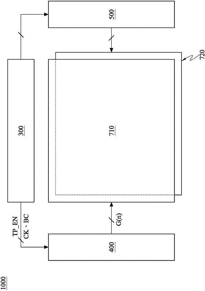
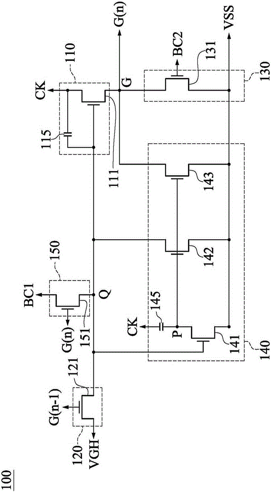
The invention discloses a sensing display device and a shift register thereof. The sensing display device comprises a time schedule controller, a sensing driver, and a scanning driver. The scanning driver is provided with multiple stages of shift temporary registers. Each shift temporary register is provided with a driving unit, a pull-up unit, a pull-down control unit, a discharging unit, and a pull-down unit. The discharging unit regulates the voltage level of a driving node according to a first control signal and a first scanning signal. A clock signal and the first control signal are same-phase periodic signals and are provided with rising edges and falling edges. The falling edge of the first control signal is prior to that of the clock signal. The pull-down unit regulates the voltage level of an output end according to a second control signal. The first control signal and the second control signal are pull-down unit periodic signals. After a shift temporary storage circuit stops, the voltage level of an internal node can be stilled charged to a driving circuit with a preset voltage level in order to prevent the internal nodes of the shift temporary storage circuit from generating electric leakage, prevent incorrect display, and output correct waveforms.

Description

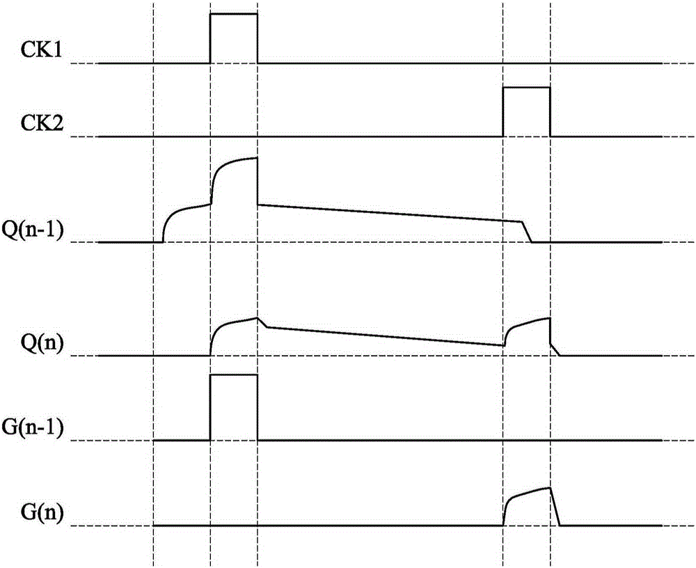
technical field [0001] The invention relates to the field of display technology, in particular to a sensing display device and a shift register thereof. Background technique [0002] Recently, various liquid crystal display products have been widely used in mobile handheld devices. And due to the wide application of smart terminal devices, the integration of touch functions into smart terminal devices has become the mainstream demand of today's products, such as general smart terminal devices. [0003] Please refer to figure 1 , the existing smart terminal device with touch display function will start the touch driver for touch driving during the display pause period, such as figure 1 as shown, figure 1 It is a waveform schematic diagram of an existing shift register with a touch display function. The display panel has multiple scan lines, and the scan driver includes a multi-level shift register circuit. The clock signal CK and the scan signal G(n-1) , G(n), and driving...

Claims


Application Information

Patent Timeline
Patent Type & Authority Applications(China)
IPC IPC(8): G11C19/28G09G3/36
CPCG09G3/36G11C19/28G06F3/04166G09G3/20G09G3/3677G09G2310/0267G09G2310/0286
Inventor 柯健专蔡孟杰
Owner AU OPTRONICS CORP
Learn More