

Processing device and method for high-precision inductor
A processing device and inductor technology, which is applied in the manufacture of inductors, inductors/transformers/magnets, circuits, etc., can solve problems such as deviations, achieve precise control of inductance, improve production efficiency and product quality, and improve batch consistency Effect
- Summary
- Abstract
- Description
- Claims
- Application Information
AI Technical Summary
Problems solved by technology
Method used
Image

Examples
Embodiment 1
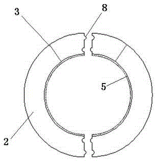
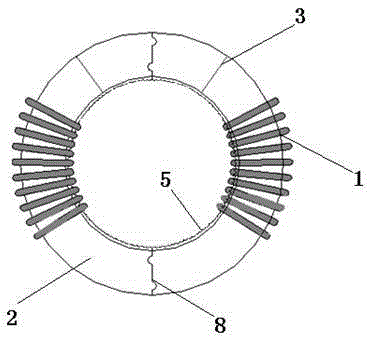
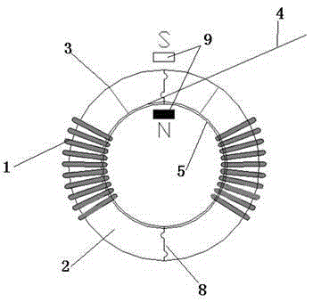
[0028] Such as Figure 3-4 As shown, a high-precision inductor processing device driven by a magnetic field, first uses special equipment to process a fan-shaped copper wire coil 1, and cooperates with two semi-circular annular shells 2 that can be rotated on the inner circumference. The coil 1 is assembled on the casing 2, and the magnetic strip 4 is wound into the rotatable part of the casing 2 through the window 3, that is, the inner circumferential groove 5, and its structure is similar to a tape measure. By applying an external magnetic field7 (eg figure 1 As shown, the axial section of the semi-circular shell 2 is placed in the magnetic field 9), and is wound by a height-adjustable brush 10. On the good copper wire coil 1, when the inductance reaches the actual required value, the brush 6 is controlled by the program command to stop the power supply, and then the winding process of the inductor is completed.
[0029] Since the copper wire coil 1 used in the same batch ...
Embodiment 2
[0032] Such as Figure 5-6 As shown, a mechanically driven high-precision inductor processing device uses a fan-shaped copper wire coil 1 processed by special equipment, and two rotatable shells 2 on the inner periphery of the special purpose, that is, there is a groove 5 on the inner circumference of the shell 2, and the groove There is a ring gear 6 inside the 5, the ring gear 6 meshes with a pair of gears 7, the copper wire coil 1 is assembled on the shell 2, and the magnetic strip 4 is wound on the rotatable part of the shell 2 through the window 3, usually by glue The process fixes the ring gear 6, and then winds it through the gear 7. The number of rotations of the winding is connected to the wound coil 1 by the instrument for testing the inductance. When the inductance reaches the actual required value, the gear is controlled by the program command. 7. Stop the rotation and complete the winding of the inductor.
[0033] Since the copper wire coil 1 used in the same bat...
PUM
 Abstract
Description
Claims
Application Information