Blower

一种送风机、风扇的技术,应用在机械设备、机器/发动机、液体燃料发动机等方向,能够解决价格高等问题

Active Publication Date: 2016-02-24
DENSO CORP
View PDF9 Cites 2 Cited by
  • Summary
  • Abstract
  • Description
  • Claims
  • Application Information

AI Technical Summary

Problems solved by technology

There is a countermeasure to use a rubber material that is not easily corroded by copper powder, but such rubber material is expensive

Method used


Image

  • Blower
  • Blower

Examples


Embodiment Construction

[0018] One embodiment of the present invention will be described.

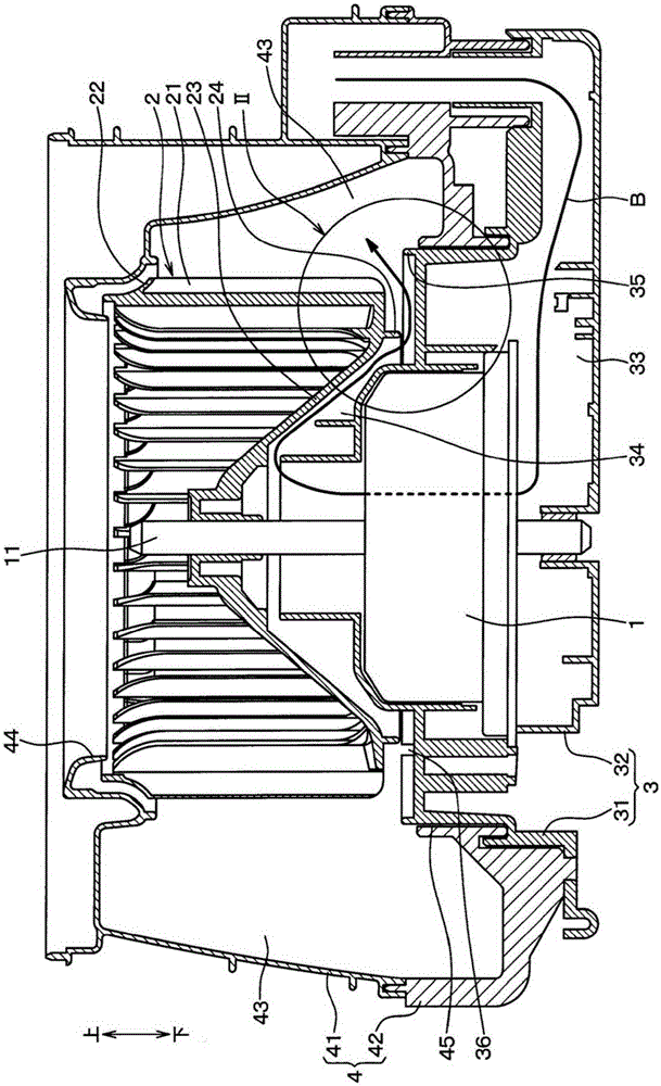
[0019] Such as figure 1 As shown, the air blower includes: a motor 1 having copper brushes; a resin fan 2 that blows air by rotating the motor 1; a resin motor case 3 that accommodates the motor 1; and a resin housing 3 that accommodates the fan 2. Made fan housing 4. In addition, below, the axial direction of the rotating shaft 11 of the electric motor 1 is called a rotating axial direction.

[0020] The fan 2 is provided with a plurality of plate-shaped blades 21 around the rotating shaft 11 . One end side of the blade 21 in the rotational axis, that is, an end portion on the suction port 44 side described later is connected by an annular side plate 22 . In addition, the other end of the blade 21 in the rotational axis is connected by a main plate 23 .

[0021] The main plate 23 has a substantially conical shape in which one end side in the rotational axis, that is, the side plate 22 side protrudes. In ...


PUM


Abstract

Provided is a blower designed such that backflow of air from a blower passage (43) into an exhaust passage (34) is prevented by a fan-side rib (24) and an electric motor casing-side rib (35), wherein the electric motor casing-side rib (35) is formed to the outside of a fan (2) in the diametrical direction of the fan, such that there is a long distance (D) in the diametrical direction of the fan between the fan-side rib (24) and the electric motor casing-side rib (35). In so doing, the flow of air for cooling the electric motor is largely unimpeded, and sufficient air for cooling the electric motor can be ensured. As a result, the electric motor (1) can be sufficiently cooled, minimizing wear of the brushes, and inflow of copper dust from the brush material into the blower passage (43) together with the air for cooling the electric motor can be minimized.

Description

[0001] Cross-reference of related applications [0002] This application is based on Japanese Patent Application No. 2013-145684 filed on July 11, 2013, the contents of which are incorporated herein by reference. technical field [0003] The present invention relates to a blower in which a fan generating air flow is driven by a motor with brushes. Background technique [0004] A blower used in a conventional air conditioner for a vehicle introduces part of the air blown into the vehicle cabin into the inside of the motor as motor cooling air to cool the motor. [0005] In addition, the air for cooling the motor passing through the inside of the motor returns to the air supply passage through the cooling air discharge passage formed between the fan and the motor case. [0006] In addition, fan side ribs protruding toward the cooling air discharge passage are formed on the fan, and motor case side ribs protruding toward the cooling air discharge passage are formed on the moto...

Claims


Application Information

Patent Timeline
Patent Type & Authority Applications(China)
IPC IPC(8): F04D29/70F04D29/28F04D29/42F04D29/58
CPCF04D25/082F04D29/282F04D29/4226F04D29/083F04D29/5806F04D17/16F04D17/10F04D25/06
Inventor 冈部聪太
Owner DENSO CORP
Why Eureka
Try Eureka