Welding equipment and combined welding method for combined welding

A technology of welding equipment and welding method, which is applied in the direction of welding equipment, auxiliary welding equipment, welding/cutting auxiliary equipment, etc., can solve the problems of difficult operation, inconsistent pressing force, and low efficiency of the method, so as to improve welding quality and ensure Welding precision, achieve the effect of repeated positioning

Active Publication Date: 2017-10-13
TRUKING TECH LTD
View PDF10 Cites 0 Cited by
  • Summary
  • Abstract
  • Description
  • Claims
  • Application Information

AI Technical Summary

Problems solved by technology

[0002] In the field of combined welding technology, the welding equipment is used to combine the base metal and the sub-pieces set on the base material. If there are movement and positioning errors of the parts, generally the lead wire is artificially marked on the base metal first, and the sub-piece placement area is divided, and then the sub-pieces are placed in this area for welding. During the welding process, this method cannot guarantee the accuracy of the base metal. The position relative to the sub-parts is relatively fixed, and positioning errors are likely to occur, resulting in welding deviation; at the same time, due to the inconsistency of the pressing force between the base metal and the sub-parts during welding, it is easy to cause the welding to be too tight or too loose, causing welding deformation, and it is also easy to produce Partial deviation affects the welding quality, and the operation is difficult during the welding process, which is easy to cause safety hazards
In addition, the sub-part placement area is marked on the base metal, and the efficiency of welding one by one is low

Method used


Image

  • Welding equipment and combined welding method for combined welding
  • Welding equipment and combined welding method for combined welding
  • Welding equipment and combined welding method for combined welding

Examples


Embodiment Construction

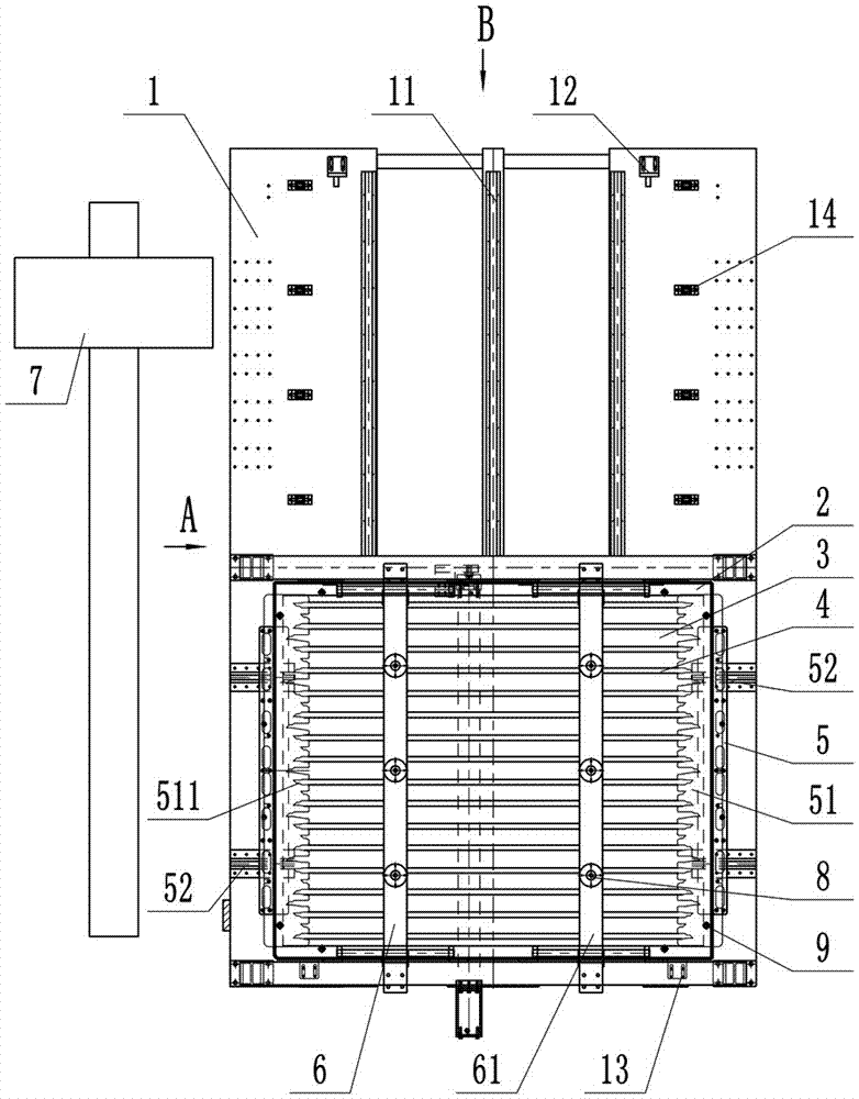
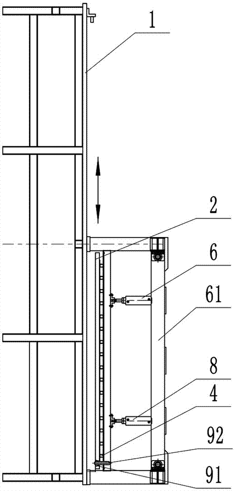
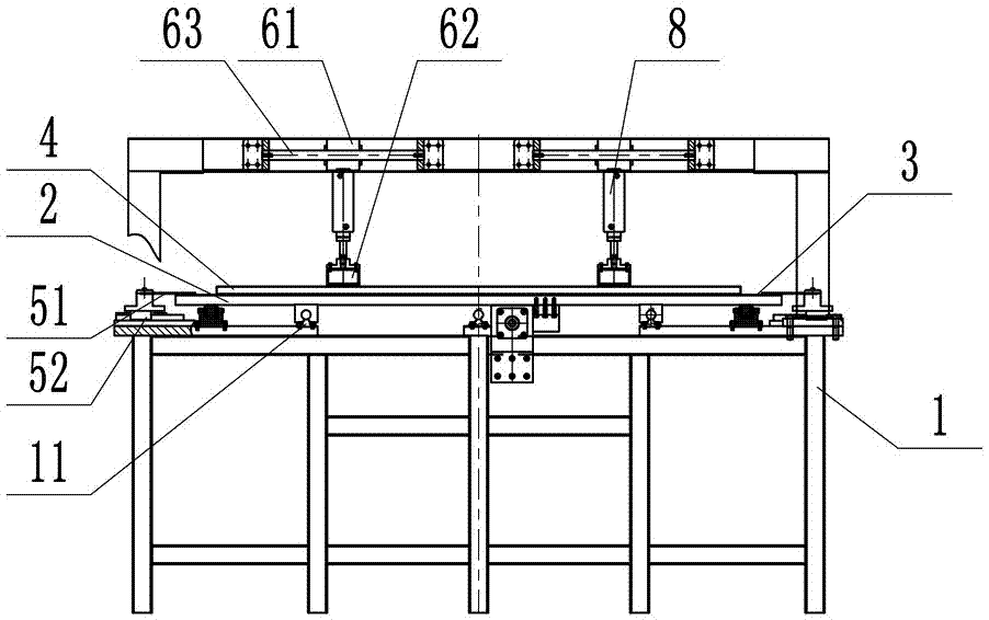
[0030] like Figure 1 to Figure 3 As shown, the welding equipment used for combined welding in this embodiment includes a machine bed 1 and a working platform 2. The working platform 2 is arranged on the machine bed 1, and the working platform 2 is used to place the base material 3. In this embodiment The welding equipment used for combined welding also includes a base metal positioning assembly 9, a sub-piece positioning assembly 5 and a pressing assembly 6. Part 4, the pressing assembly 6 presses the positioned sub-part 4 on the base material 3. The setting of the base material positioning assembly 9 and the sub-piece positioning assembly 5 effectively avoids the relative movement between the base material 3 and the sub-piece 4, and effectively realizes the reliable positioning of the sub-piece 4; the pressing assembly 6 compresses the sub-piece 4 on the The base material 3 avoids gaps between the sub-parts 4 and the base material 3, effectively improving the welding qualit...


PUM


Abstract

The invention provides a welding device and a combined welding method for combined welding. The welding equipment includes the bed of the machine tool and the working platform for placing the base metal. The working platform is set on the bed of the machine tool. A part positioning component and a pressing component for pressing the positioned part on the base material. The combined welding method includes the following steps: positioning the base metal on the working platform; placing the working platform on the welding station for positioning, placing multiple parts on the base metal, and positioning the multiple parts through the positioning splint of the part positioning assembly. The two ends of the part are clamped and positioned at the same time; the base metal and the sub-pieces are pressed by the compression component; the base metal and the sub-pieces are welded to multiple sub-pieces; The assembly weldment formed by the base metal and sub-components described below. The invention has the advantages of improving the positioning reliability of parts and welding quality.

Description

technical field [0001] The invention relates to the field of welding technology, in particular to welding equipment and a combined welding method for combined welding. Background technique [0002] In the field of combined welding technology, the welding equipment is used to combine the base metal and the sub-pieces set on the base material. If there are movement and positioning errors of the parts, generally the lead wire is artificially marked on the base metal first, and the sub-piece placement area is divided, and then the sub-pieces are placed in this area for welding. During the welding process, this method cannot guarantee the accuracy of the base metal. The position relative to the sub-parts is relatively fixed, and positioning errors are likely to occur, resulting in welding deviation; at the same time, due to the inconsistency of the pressing force between the base metal and the sub-parts during welding, it is easy to cause the welding to be too tight or too loose,...

Claims


Application Information

Patent Timeline
Patent Type & Authority Patents(China)
IPC IPC(8): B23K37/04
Inventor 周志中王仕虎
Owner TRUKING TECH LTD
Why Eureka
Try Eureka