A cylinder processing fixture

A technology for fixing devices and cylinders, applied in positioning devices, clamping devices, metal processing equipment, etc., can solve problems such as cumbersome operation, insufficient pressing force, and processing defects, so as to improve processing efficiency, increase pressing force, The effect of easy replacement

Active Publication Date: 2018-09-11
HIMILE MECHANICAL MFG
View PDF7 Cites 0 Cited by
  • Summary
  • Abstract
  • Description
  • Claims
  • Application Information

AI Technical Summary

Problems solved by technology

This kind of fixing method requires alignment and positioning during the fixing process, and the alignment of this kind of rotary workpiece is generally installed on the main shaft with a dial indicator, and the position of the workpiece is continuously adjusted through the rotation of the main shaft to perform alignment. Alignment, alignment, positioning efficiency is very low
At the same time, after alignment, it is necessary to fix the studs on the workbench one by one, press the pressure plate on the outer edge of the rotary workpiece, and then fix the pressure plate on the studs. The operation is very cumbersome and the fixing efficiency is low.
Moreover, the pressing force of this fixing method is insufficient, and the workpiece is prone to shaking during processing, resulting in processing defects.

Method used


Image

  • A cylinder processing fixture
  • A cylinder processing fixture
  • A cylinder processing fixture

Examples


Embodiment 1

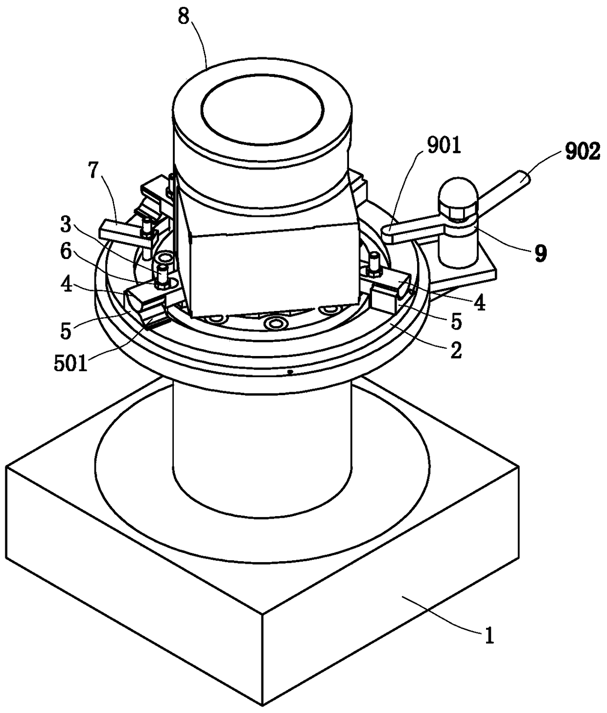
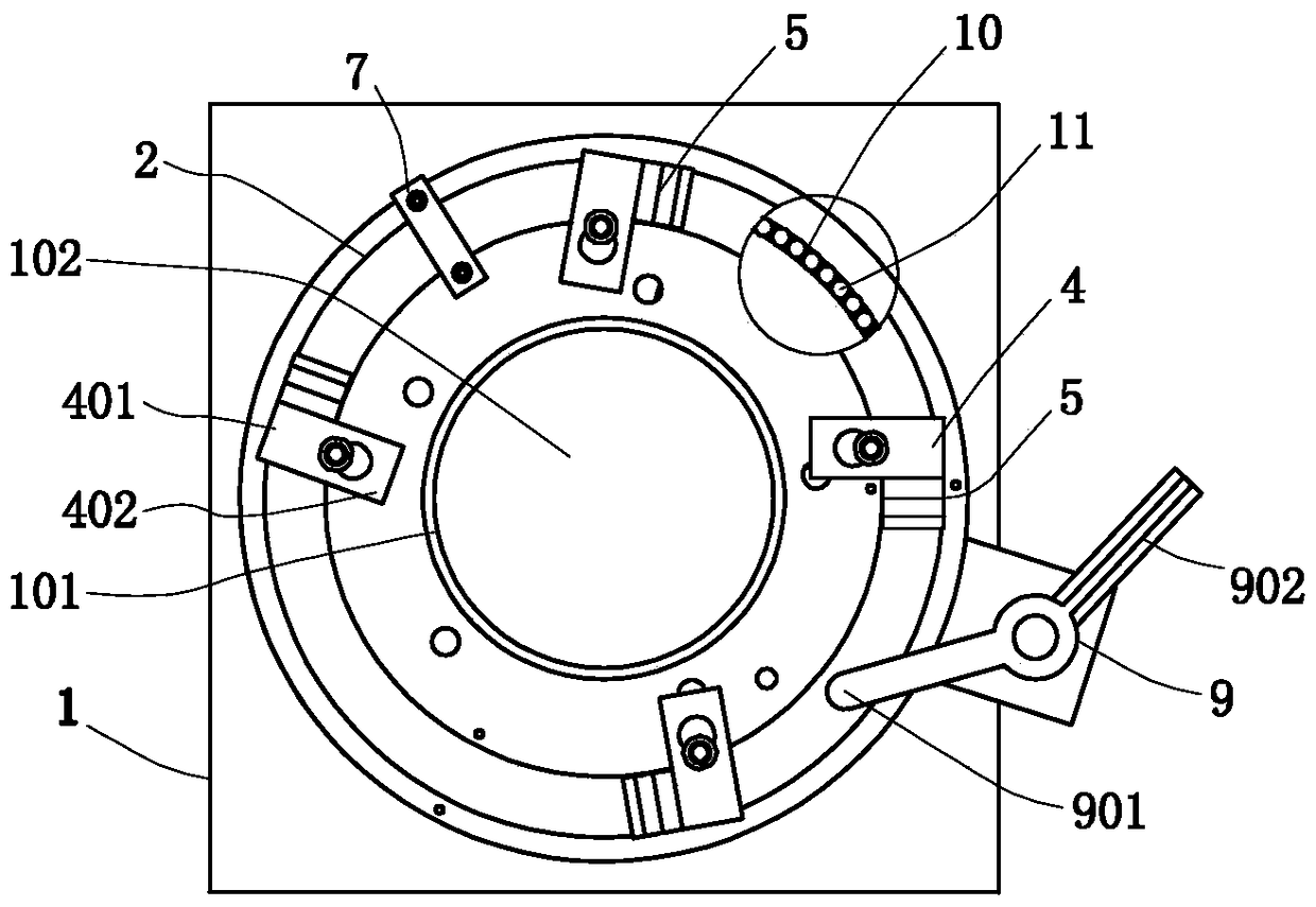
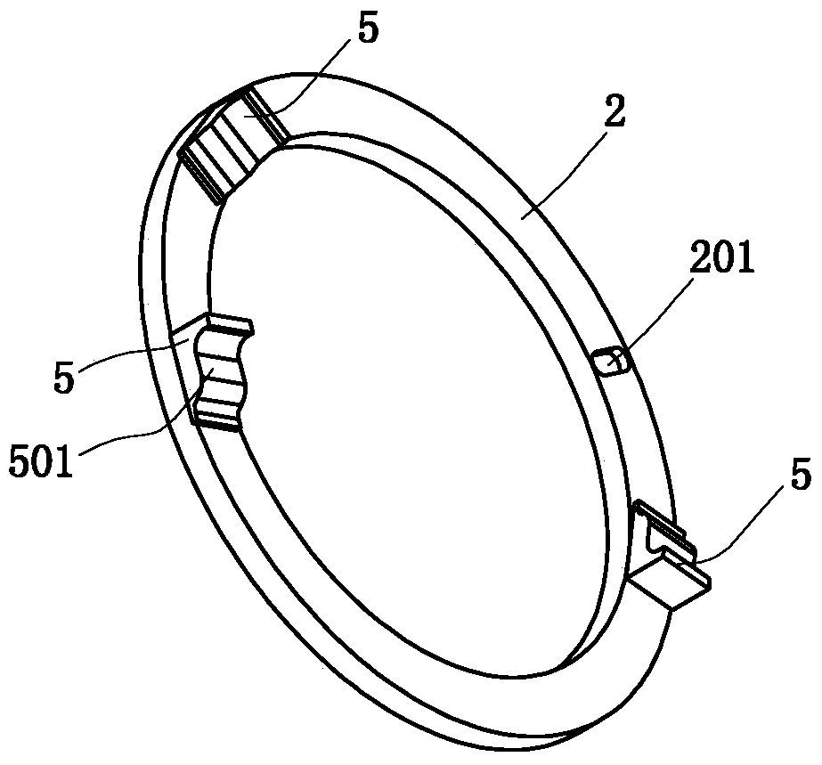
[0025] Such as Figure 1 to Figure 3 Commonly shown, the present invention provides a cylinder processing fixture, including a support base 1, the top of the support base 1 is provided with a limit groove 101 that matches the end of the outer flange of the rotary workpiece 8, directly The end of the outer flange of the rotary workpiece 8 is placed in the limit groove 101, which realizes fast alignment and positioning. A swivel 2 is installed on the outer circumference of the limit groove 101 on the support seat 1, and the swivel 2 is connected to the rotary There are a number of fixed shafts 3 fixedly installed on the support base 1 between the workpieces 8, and a pressing block 4 is constrained to be installed on each fixed shaft 3. As for the connection method between the pressing block 4 and the fixed shaft 3, specifically, it can be used In the following structure, the pressing block 4 is provided with a through hole, the fixed shaft 3 passes through the through hole and t...

Embodiment 2

[0031] The present invention provides a cylinder processing and fixing device, the structure of which is basically the same as that of Embodiment 1, the difference being that: the power device includes a driving gear driven by a motor, and a ring gear meshing with the driving gear is provided on the swivel 2 .


PUM


Abstract

The invention discloses a cylinder body machining fixing device, and belongs to the technical field of tool devices. The cylinder body machining fixing device comprises a supporting base. A limiting groove matched with the end of a flange on the outer side of a rotation workpiece is formed in the top of the supporting base. A rotation ring is arranged on the portion, located on the periphery of the limiting groove, on the supporting base in a rotating mode. A plurality of fixing shafts fixedly arranged on the supporting base are arranged between the rotation ring and the rotation workpiece. A pressing block is restrained and installed on each fixing shaft. Each pressing block comprises a force exerting end extending towards the rotation ring, and a pressing end extending to the flange on the outer side of the rotation workpiece. Wedge-shaped blocks corresponding to the pressing blocks one to one are arranged on the rotation ring. A power device used for driving the rotation ring to rotate is arranged on the supporting base. By means of the cylinder body machining fixing device, rapid alignment can be conducted, multiple pressing plates can be clamped at a time, the self-lock function is achieved, operation is simple, machining efficiency is improved, and the cylinder body machining fixing device is widely applied to machining of the rotation workpiece such as a cylinder body.

Description

technical field [0001] The invention relates to the technical field of tooling equipment, in particular to a processing auxiliary device for a rotary workpiece with an outer flange. Background technique [0002] For cylinders or cylinders of revolution with protruding outer edges, such as compressor cylinders, they need to be positioned and fixed on a workbench before machining. The traditional method is to press the outer edge of the workpiece on the workbench through the bolts and the pressure plate, so as to realize the fixing and pressing of the entire workpiece. This kind of fixing method requires alignment and positioning during the fixing process, and the alignment of this kind of rotary workpiece is generally installed on the main shaft with a dial indicator, and the position of the workpiece is continuously adjusted through the rotation of the main shaft to perform alignment. Correction, alignment and positioning efficiency is very low. At the same time, after ali...

Claims


Application Information

Patent Timeline
Patent Type & Authority Patents(China)
IPC IPC(8): B23Q3/00
CPCB23Q3/00B23Q2703/10
Inventor 张先宾张增军唐立星张兆和迟丰涛魏猛盖永礼
Owner HIMILE MECHANICAL MFG
Why Eureka
Try Eureka